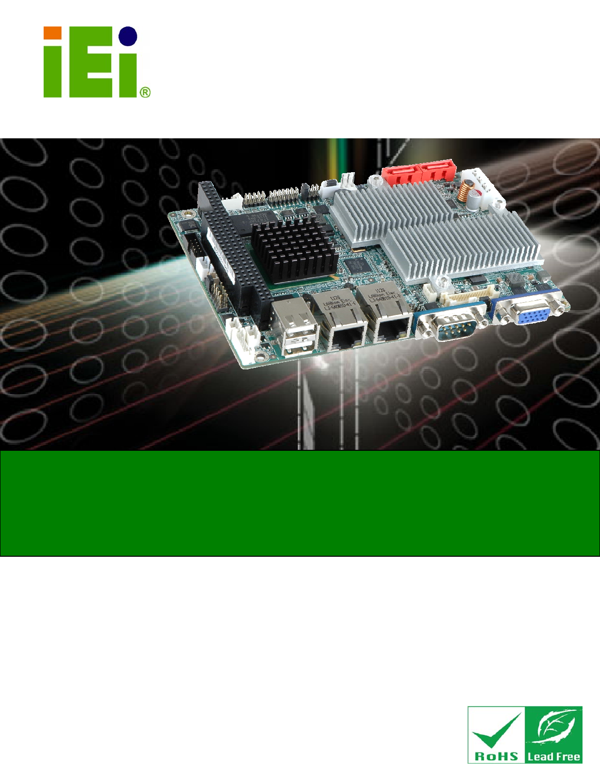
WAFER-945GSE2 3.5" Motherboard IEI Technology Corp. MODEL: WAFER-945GSE2 3.5" SBC with 1.6 HGz Intel® Atom™ N270, VGA/LVDS, Dual PCIe GbE, CF Type II, USB, SATA, On-board 1 GB Memory and PC/104 User Manual Page i Rev. 2.
WAFER-945GSE2 3.5" Motherboard Revision Date Version Changes 28 October, 2011 2.00 Updated for R20 version 20 September, 2011 1.03 Updated section 1.5 Data Flow 25 June, 2009 1.02 New photographs added 11 March, 2009 1.01 Model name update 17 February, 2009 1.
WAFER-945GSE2 3.5" Motherboard Copyright COPYRIGHT NOTICE The information in this document is subject to change without prior notice in order to improve reliability, design and function and does not represent a commitment on the part of the manufacturer. In no event will the manufacturer be liable for direct, indirect, special, incidental, or consequential damages arising out of the use or inability to use the product or documentation, even if advised of the possibility of such damages.
WAFER-945GSE2 3.5" Motherboard Table of Contents 1 INTRODUCTION.......................................................................................................... 1 1.1 INTRODUCTION........................................................................................................... 2 1.2 MODEL VARIATIONS ................................................................................................... 2 1.3 CONNECTORS ...........................................................................
WAFER-945GSE2 3.5" Motherboard 3.2.10 LED Connector .............................................................................................. 26 3.2.11 LVDS LCD Connector.................................................................................... 27 3.2.12 PC/104 Connector ......................................................................................... 28 3.2.13 PC/104 Power Input Connector..................................................................... 29 3.2.
WAFER-945GSE2 3.5" Motherboard 4.6.6 USB Cable (Dual Port without Bracket) (Optional)........................................ 55 4.7 EXTERNAL PERIPHERAL INTERFACE CONNECTION ................................................... 56 4.7.1 LAN Connection............................................................................................... 57 4.7.2 Serial Device Connection ................................................................................ 57 4.7.3 USB Connection (Dual Connector) ...........
WAFER-945GSE2 3.5" Motherboard 5.8 EXIT ......................................................................................................................... 99 6 SOFTWARE DRIVERS ............................................................................................ 101 6.1 AVAILABLE SOFTWARE DRIVERS ............................................................................ 102 6.2 STARTING THE DRIVER PROGRAM .......................................................................... 102 6.
WAFER-945GSE2 3.5" Motherboard D.3 ASSEMBLY LANGUAGE SAMPLES........................................................................... 154 D.3.1 Enable the DIO Input Function .................................................................... 154 D.3.2 Enable the DIO Output Function.................................................................. 155 E WATCHDOG TIMER............................................................................................... 156 F HAZARDOUS MATERIALS DISCLOSURE........
WAFER-945GSE2 3.5" Motherboard List of Figures Figure 1-1: WAFER-945GSE2 ........................................................................................................2 Figure 1-2: Connectors ..................................................................................................................3 Figure 1-3: WAFER-945GSE2 Dimensions (mm).........................................................................6 Figure 1-4: External Interface Panel Dimensions (mm) ........................
WAFER-945GSE2 3.5" Motherboard Figure 4-1: CF Card Installation ..................................................................................................42 Figure 4-2: AT/ATX Power Select Jumper Location..................................................................44 Figure 4-3: CF Card Setup Jumper Location .............................................................................45 Figure 4-4: Clear BIOS Jumper Location ......................................................................
WAFER-945GSE2 3.5" Motherboard Figure 6-19: Audio Driver Installation File Extraction............................................................ 116 Figure 6-20: Audio Driver Installation Welcome Screen........................................................ 116 Figure 6-21: Audio Driver Installation...................................................................................... 116 Figure 6-22: Audio Driver Installation Complete ....................................................................
WAFER-945GSE2 3.5" Motherboard Figure B-32: Restore System Backup Complete Window ..................................................... 144 Figure B-33: Symantec Ghost Window ...................................................................................
WAFER-945GSE2 3.5" Motherboard List of Tables Table 1-1: WAFER-945GSE2 Model Variations............................................................................2 Table 1-2: WAFER-945GSE2 Specifications ................................................................................9 Table 2-1: Packing List.................................................................................................................13 Table 2-2: Optional Items............................................................
WAFER-945GSE2 3.5" Motherboard Table 3-27: VGA Connector Pinouts...........................................................................................38 Table 4-1: Jumpers .......................................................................................................................43 Table 4-2: AT/ATX Power Select Jumper Settings ....................................................................44 Table 4-3: CF Card Setup Jumper Settings ......................................................
WAFER-945GSE2 3.5" Motherboard BIOS Menus BIOS Menu 1: Main .......................................................................................................................64 BIOS Menu 2: Advanced ..............................................................................................................65 BIOS Menu 3: CPU Configuration ...............................................................................................66 BIOS Menu 4: IDE Configuration...................................
WAFER-945GSE2 3.
WAFER-945GSE2 3.5" Motherboard 1.1 Introduction Figure 1-1: WAFER-945GSE2 The WAFER-945GSE2 3.5” motherboards are embedded 45 nm Intel® Atom™ processor platforms. The Intel® Atom™ processor N270 embedded on the WAFER-945GSE2 has a 1.60 GHz clock speed, a 533 MHz FSB and a 512 KB L2 cache. The WAFER-945GSE2 also includes onboard 1.0 GB DDR2 SDRAM. The board comes with an LVDS connector and supports both 18-bit and 36-bit single channel LVDS screens.
WAFER-945GSE2 3.5" Motherboard 1.3 Connectors The connectors on the WAFER-945GSE2 are shown in the figure below.
WAFER-945GSE2 3.
WAFER-945GSE2 3.5" Motherboard 1.4 Dimensions 1.4.
WAFER-945GSE2 3.5" Motherboard Figure 1-3: WAFER-945GSE2 Dimensions (mm) 1.4.2 External Interface Panel Dimensions External peripheral interface connector panel dimensions are shown in Figure 1-4.
WAFER-945GSE2 3.5" Motherboard 1.5 Data Flow Figure 1-5 shows the data flow between the system chipset, the CPU and other 6 components installed on the motherboard.
WAFER-945GSE2 3.5" Motherboard 1.6 Technical Specifications The WAFER-945GSE2 technical specifications are listed below. Specification/Model WAFER-945GSE2 Form Factor 3.5” System CPU 45 nm 1.6 GHz Intel® Atom™ N270 Front Side Bus 533 MHz (FSB) System Chipset Northbridge: Intel® 945GSE Southbridge: Intel® ICH7-M Memory On-board 533 MHz 1.0 GB DDR2 SDRAM CompactFlash® One CompactFlash® Type II socket Super I/O ITE IT8718 Display Intel® Generation 3.
WAFER-945GSE2 3.5" Motherboard Specification/Model WAFER-945GSE2 Watchdog Timer Software programmable supports 1~255 sec. system reset Power Supply 5 V only 12 V for LCD/system fan AT and ATX support Power 5V @ 3.1 A (1.6 GHz Intel® Atom™ N270 with on-board 1.
WAFER-945GSE2 3.
WAFER-945GSE2 3.5" Motherboard 2.1 Anti-static Precautions WARNING! Static electricity can destroy certain electronics. Make sure to follow the ESD precautions to prevent damage to the product, and injury to the user. Make sure to adhere to the following guidelines: Wear an anti-static wristband: Wearing an anti-static wristband can prevent electrostatic discharge. Self-grounding: Touch a grounded conductor every few minutes to discharge any excess static buildup.
WAFER-945GSE2 3.5" Motherboard 2.3 Packing List NOTE: If any of the components listed in the checklist below are missing, do not proceed with the installation. Contact the IEI reseller or vendor the WAFER-945GSE2 was purchased from or contact an IEI sales representative directly by sending an email to sales@iei.com.tw.
WAFER-945GSE2 3.5" Motherboard Quantity Item and Part Number 2 Plastic intermediate pole for PC/104 (20mm) 1 One Key Recovery CD Image (P/N: IEI-7B000-000478-RS) 1 Utility CD 1 Quick Installation Guide Table 2-1: Packing List 2.
WAFER-945GSE2 3.
WAFER-945GSE2 3.5" Motherboard 3.1 Peripheral Interface Connectors This chapter details all the jumpers and connectors. 3.1.1 WAFER-945GSE2 Layout The figures below show all the connectors and jumpers.
WAFER-945GSE2 3.5" Motherboard 3.1.2 Peripheral Interface Connectors The table below lists all the connectors on the board.
WAFER-945GSE2 3.5" Motherboard 3.1.3 External Interface Panel Connectors The table below lists the connectors on the external I/O panel. Connector Type Label Ethernet connector RJ-45 LAN1 Ethernet connector RJ-45 LAN2 RS-232 serial port connector Male DB-9 COM1 Dual USB port USB port USB_C45 VGA port connector 15-pin female VGA1 Table 3-2: Rear Panel Connectors 3.2 Internal Peripheral Connectors The section describes all of the connectors on the WAFER-945GSE2. 3.2.
WAFER-945GSE2 3.5" Motherboard Pin Description 1 +12V 2 GND 3 GND 4 +5V Table 3-3: ATX Power Connector Pinouts 3.2.2 ATX Power Supply Enable Connector CN Label: ATXCTL1 CN Type: 3-pin wafer CN Location: See Figure 3-4 CN Pinouts: See Table 3-4 The ATX power supply enable connector enables the WAFER-945GSE2 to be connected to an ATX power supply. In default mode, the WAFER-945GSE2 can only use an AT power supply.
WAFER-945GSE2 3.5" Motherboard Pin Description 2 GND 3 PS-ON Table 3-4: ATX Power Supply Enable Connector Pinouts 3.2.3 Audio Connector (10-pin) CN Label: AUDIO1 CN Type: 10-pin header CN Location: See Figure 3-5 CN Pinouts: See Table 3-5 The 10-pin audio connector is connected to external audio devices including speakers and microphones for the input and output of audio signals to and from the system.
WAFER-945GSE2 3.5" Motherboard 3.2.4 Backlight Inverter Connector CN Label: INVERTER1 CN Type: 5-pin wafer CN Location: See Figure 3-6 CN Pinouts: See Table 3-6 The backlight inverter connectors provide the backlights on the LCD display connected to the WAFER-945GSE2 with +12V of power.
WAFER-945GSE2 3.5" Motherboard 3.2.5 Battery Connector CAUTION: Risk of explosion if battery is replaced by and incorrect type. Only certified engineers should replace the on-board battery. Dispose of used batteries according to instructions and local regulations. CN Label: BAT1 CN Type: 2-pin wafer CN Location: See Figure 3-7 CN Pinouts: See Table 3-7 This is connected to the system battery. The battery provides power to the system clock to retain the time when power is turned off.
WAFER-945GSE2 3.5" Motherboard 3.2.6 CompactFlash® Socket CN Label: CF1 CN Type: 50-pin header CN Location: See Figure 3-8 CN Pinouts: See Table 3-8 A CF Type I or Type II memory card can be inserted to the CF socket on the WAFER-945GSE2.
WAFER-945GSE2 3.5" Motherboard Pin Description Pin Description 16 A4 41 RESET# 17 A3 42 WAIT# 18 A2 43 INPACK# 19 A1 44 REG# 20 A0 45 BVD2 21 D0 46 BVD1 22 D1 47 D8 23 D2 48 D9 24 IOCS16# 49 D10 25 CD2# 50 GND2 Table 3-8: CF Card Socket Pinouts 3.2.7 Digital Input/Output (DIO) Connector CN Label: DIO1 CN Type: 10-pin header CN Location: See Figure 3-9 CN Pinouts: See Table 3-9 The digital input/output connector is managed through a Super I/O chip.
WAFER-945GSE2 3.5" Motherboard Pin Description Pin Description 1 GND 2 VCC 3 Output 3 4 Output 2 5 Output 1 6 Output 0 7 Input 3 8 Input 2 9 Input 1 10 Input 0 Table 3-9: Digital I/O Connector Pinouts 3.2.8 Fan Connector (+12V, 3-pin) CN Label: CPU_FAN1 CN Type: 3-pin wafer CN Location: See Figure 3-10 CN Pinouts: See Table 3-10 The cooling fan connector provides a 12V, 500mA current to the cooling fan.
WAFER-945GSE2 3.5" Motherboard PIN NO. DESCRIPTION 2 +12V 3 Fan Speed Detect Table 3-10: +12V Fan Connector Pinouts 3.2.9 Keyboard/Mouse Connector CN Label: KB_MS1 CN Type: 6-pin wafer CN Location: See Figure 3-11 CN Pinouts: See Table 3-11 The keyboard and mouse connector can be connected to a standard PS/2 cable or PS/2 Y-cable to add keyboard and mouse functionality to the system.
WAFER-945GSE2 3.5" Motherboard Pin Description 6 GROUND Table 3-11: Keyboard/Mouse Connector Pinouts 3.2.10 LED Connector CN Label: LED_C1 CN Type: 6-pin wafer CN Location: See Figure 3-12 CN Pinouts: See Table 3-12 The LED connector connects to an HDD indicator LED and a power LED on the system chassis to inform the user about HDD activity and the power on/off status of the system.
WAFER-945GSE2 3.5" Motherboard 3.2.11 LVDS LCD Connector CN Label: LVDS1 CN Type: 30-pin crimp CN Location: See Figure 3-13 CN Pinouts: See Table 3-13 The 30-pin LVDS LCD connector can be connected to single channel or dual channel, 18-bit or 36-bit LVDS panel.
WAFER-945GSE2 3.5" Motherboard Pin Description Pin Description 21 B_CK 22 B_CK# 23 NC 24 NC 25 GND5 26 GND6 27 VCC_LCD 28 VCC_LCD 29 VCC_LCD 30 VCC_LCD Table 3-13: LVDS LCD Port Connector Pinouts 3.2.12 PC/104 Connector CN Label: CN2 CN Type: 104-pin PC/104 slot CN Location: See Figure 3-14 CN Pinouts: See Table 3-14 and Table 3-15 6 The PC/104 connector is for attaching a PC/104 expansion card.
WAFER-945GSE2 3.
WAFER-945GSE2 3.5" Motherboard The PC/104 power input connector provides power to the PC/104 expansion module installed on the PC/104 slot. Figure 3-15: PC/104 Power Input Connector Pinouts Pin Description 1 -5V 2 GND 3 -12V Table 3-16: PC/104 Power Input Connector Pinouts 3.2.
WAFER-945GSE2 3.5" Motherboard Pin Description 1 Power Switch 2 GND Table 3-17: Power Button Connector Pinouts 3.2.15 Reset Button Connector CN Label: RESET1 CN Type: 2-pin wafer CN Location: See Figure 3-17 CN Pinouts: See Table 3-18 The reset button connector is connected to a reset switch on the system chassis to enable users to reboot the system when the system is turned on.
WAFER-945GSE2 3.5" Motherboard CN Location: See Figure 3-18 CN Pinouts: See Table 3-19 The SATA drive connectors can be connected to SATA drives and support up to 3Gb/s data transfer rate. Figure 3-18: SATA Drive Connector Locations Pin Description 1 GND 2 TX+ 3 TX- 4 GND 5 RX- 6 RX+ 7 GND Table 3-19: SATA Drive Connector Pinouts 3.2.
WAFER-945GSE2 3.5" Motherboard The 14-pin serial port connector connects to the COM2 serial communications channels. COM2 is a multi function channel. In default mode COM2 is an RS-232 serial communication channel but, with the COM2 function select jumper, can be configured as either an RS-422 or RS-485 serial communications channel.
WAFER-945GSE2 3.5" Motherboard The 8-pin SPI Flash connector is used to flash the BIOS. Figure 3-20: SPI Flash Connector Pin Description Pin Description 1 VCC 2 GND 3 CS# 4 CLOCK 5 SO 6 SI 7 NC 8 NC Table 3-21: SPI Flash Connector 3.2.19 USB Connectors (Internal) CN Label: USB01 and USB23 CN Type: 8-pin header CN Location: See Figure 3-21 CN Pinouts: See Table 3-22 The 2x4 USB pin connectors each provide connectivity to two USB 1.1 or two USB 2.0 ports.
WAFER-945GSE2 3.5" Motherboard Figure 3-21: USB Connector Pinout Locations Pin Description Pin Description 1 VCC 2 GND 3 DATA- 4 DATA+ 5 DATA+ 6 DATA- 7 GND 8 VCC Table 3-22: USB Port Connector Pinouts 3.3 External Peripheral Interface Connector Panel The figure below shows the external peripheral interface connector (EPIC) panel.
WAFER-945GSE2 3.5" Motherboard 3.3.1 Ethernet Connectors CN Label: LAN1 and LAN2 CN Type: RJ-45 connector CN Location: See Figure 3-22 CN Pinouts: See Table 3-23 The WAFER-945GSE2 is equipped with two built-in RJ-45 Ethernet controllers. The controllers can connect to the LAN through two RJ-45 LAN connectors. There are two LEDs on the connector indicating the status of LAN.
WAFER-945GSE2 3.5" Motherboard 3.3.2 Serial Port Connectors (COM1) CN Label: COM1 CN Type: DB-9 connector CN Location: See Figure 3-22 CN Pinouts: See Table 3-25 and Figure 3-24 The serial port connects to a RS-232 serial communications device. Pin Description Pin Description 1 DCD 6 DSR 2 RX 7 RTS 3 TX 8 CTS 4 DTR 9 RI 5 GND Table 3-25: RS-232 Serial Port (COM 1) Pinouts Figure 3-24: COM1 Pinout Locations 3.3.
WAFER-945GSE2 3.5" Motherboard Pin Description Pin Description 1 VCC 5 VCC 2 DATA- 6 DATA- 3 DATA+ 7 DATA+ 4 GND 8 GND Table 3-26: USB Port Pinouts 3.3.4 VGA Connector CN Label: VGA1 CN Type: 15-pin Female CN Location: See Figure 3-22 CN Pinouts: See Figure 3-25 and Table 3-27 The WAFER-945GSE2 has a single 15-pin female connector for connectivity to standard display devices.
WAFER-945GSE2 3.
WAFER-945GSE2 3.5" Motherboard 4.1 Anti-static Precautions WARNING: Failure to take ESD precautions during the installation of the WAFER-945GSE2 may result in permanent damage to the WAFER-945GSE2 and severe injury to the user. Electrostatic discharge (ESD) can cause serious damage to electronic components, including the WAFER-945GSE2. Dry climates are especially susceptible to ESD.
WAFER-945GSE2 3.5" Motherboard WARNING: The installation instructions described in this manual should be carefully followed in order to prevent damage to the components and injury to the user. Before and during the installation please DO the following: Read the user manual: o The user manual provides a complete description of the WAFER-945GSE2 installation instructions and configuration options. Wear an electrostatic discharge cuff (ESD): o Electronic components are easily damaged by ESD.
WAFER-945GSE2 3.5" Motherboard Step 1: Locate the CF card socket. Place the WAFER-945GSE2 on an anti-static pad with the solder side facing up. Locate the CF card. Step 2: Align the CF card. Make sure the CF card is properly aligned with the CF socket. Step 3: Insert the CF card. Gently insert the CF card into the socket making sure the socket pins are properly inserted into the socket. See Figure 4-1.
WAFER-945GSE2 3.5" Motherboard 4.4 Jumper Settings NOTE: A jumper is a metal bridge used to close an electrical circuit. It consists of two or three metal pins and a small metal clip (often protected by a plastic cover) that slides over the pins to connect them. To CLOSE/SHORT a jumper means connecting the pins of the jumper with the plastic clip and to OPEN a jumper means removing the plastic clip from a jumper. The hardware jumpers must be set before installation. Jumpers are shown in Table 4-1.
WAFER-945GSE2 3.5" Motherboard Jumper Label: ATXCTL1 Jumper Type: 3-pin header Jumper Settings: See Table 4-2 Jumper Location: See Figure 4-2 The AT/ATX Power Select jumper specifies the systems power mode as AT or ATX. Setting Description Short 2-3 Use AT power (Default) OFF Use ATX power Table 4-2: AT/ATX Power Select Jumper Settings Figure 4-2: AT/ATX Power Select Jumper Location 4.4.
WAFER-945GSE2 3.5" Motherboard Setting Description OFF Slave (Default) Short 1-2 Master Table 4-3: CF Card Setup Jumper Settings Figure 4-3: CF Card Setup Jumper Location 4.4.3 Clear CMOS Jumper Jumper Label: J_CMOS1 Jumper Type: 3-pin header Jumper Settings: See Table 4-4 Jumper Location: See Figure 4-4 If the WAFER-945GSE2 fails to boot due to improper BIOS settings, the clear CMOS jumper clears the CMOS data and resets the system BIOS information.
WAFER-945GSE2 3.5" Motherboard Setting Description Short 1-2 Keep CMOS Setup (Default) Short 2-3 Clear CMOS Setup Table 4-4: Clear BIOS Jumper Settings Figure 4-4: Clear BIOS Jumper Location 4.4.4 COM 2 Function Select Jumper Jumper Label: JP1 Jumper Type: 8-pin header Jumper Settings: See Table 4-5 Jumper Location: See Figure 4-5 The COM 2 Function Select jumper sets the communication protocol used by the second serial communications port (COM 2) as RS-232, RS-422 or RS-485.
WAFER-945GSE2 3.5" Motherboard Figure 4-5: COM 2 Function Select Jumper Location 4.4.5 LVDS Voltage Selection WARNING: Permanent damage to the screen and WAFER-945GSE2 may occur if the wrong voltage is selected with this jumper. Please refer to the user guide that came with the monitor to select the correct voltage.
WAFER-945GSE2 3.5" Motherboard Figure 4-6: LVDS Voltage Selection Jumper Pinout Locations 4.5 Chassis Installation 4.5.1 Airflow WARNING: Airflow is critical to the cooling of the CPU and other onboard components. The chassis in which the WAFER-945GSE2 must have air vents to allow cool air to move into the system and hot air to move out. The WAFER-945GSE2 must be installed in a chassis with ventilation holes on the sides allowing airflow to travel through the heat sink surface.
WAFER-945GSE2 3.5" Motherboard NOTE: IEI has a wide range of backplanes available. Please contact your WAFER-945GSE2 vendor, reseller or an IEI sales representative at sales@iei.com.tw or visit the IEI website (http://www.ieiworld.com.tw) 2 2 to find out more about the available chassis. 4.5.2 Motherboard Installation To install the WAFER-945GSE2 motherboard into the chassis please refer to the reference material that came with the chassis. 4.
WAFER-945GSE2 3.5" Motherboard Figure 4-7: SATA Drive Cable Connection Step 3: Connect the cable to the SATA disk. Connect the connector on the other end of the cable to the connector at the back of the SATA drive. See Figure 4-8. Step 4: Connect the SATA power cable (optional). Connect the SATA power connector to the back of the SATA drive. See Figure 4-8.
WAFER-945GSE2 3.5" Motherboard Figure 4-8: SATA Power Cable Connection The SATA power cable can be bought from IEI. See Optional Items in Section 2.4. 4.6.2 Dual RS-232 Cable Connection (w/o bracket) (Optional) The dual RS-232 cable consists of two connectors attached to two independent cables. Each cable is then attached to a D-sub 9-pin male connector. To install the dual RS-232 cable, please follow the steps below. Step 1: Locate the connectors.
WAFER-945GSE2 3.5" Motherboard Figure 4-9: Dual RS-232 Cable Installation Step 3: Secure the connectors. Both single RS-232 connectors have two retention screws that must be secured to a chassis or bracket. Step 4: Connect the serial device. Once the single RS-232 connectors are connected to a chassis or bracket, a serial communications device can be connected to the system. 4.6.3 Keyboard/Mouse Y-cable Connector The WAFER-945GSE2 is shipped with a keyboard/mouse Y-cable connector.
WAFER-945GSE2 3.5" Motherboard the keyboard/mouse connector on the WAFER-945GSE2, connect the cable connector to the on-board connectors. See Figure 4-10. Figure 4-10: Keyboard/mouse Y-cable Connection Step 4: Attach PS/2 connectors to the chassis. The keyboard/mouse Y-cable connector is connected to two PS/2 connectors. To secure the PS/2 connectors to the chassis please refer to the installation instructions that came with the chassis. Step 5: Connect the keyboard and mouse.
WAFER-945GSE2 3.5" Motherboard 4.6.4 Audio Kit Installation The Audio Kit that came with the WAFER-945GSE2 connects to the 10-pin audio connector on the WAFER-945GSE2. The audio kit consists of three audio jacks. One audio jack, Mic In, connects to a microphone. The remaining two audio jacks, Line-In and Line-Out, connect to two speakers. To install the audio kit, please refer to the steps below: Step 1: Locate the audio connector. The location of the 10-pin audio connector is shown in Chapter 3.
WAFER-945GSE2 3.5" Motherboard Figure 4-12: WAFER-945GSE2 PC/104 module installation Step 4: Remove retention nuts. Remove the two nuts securing the heatsink and two nuts securing the WAFER-945GSE2 to the chassis. Step 5: Attach intermediate poles. Insert the two short plastic intermediate poles into the bolts securing the heatsink. Insert the two tall plastic intermediate poles. Step 6: Align the PC/104 connector.
WAFER-945GSE2 3.5" Motherboard Step 1: Locate the connectors. The locations of the USB connectors are shown in Chapter 3. WARNING: If the USB pins are not properly aligned, the USB device can burn out. Step 2: Align the connectors. The cable has two connectors. Correctly align pin 1on each cable connector with pin 1 on the WAFER-945GSE2 USB connector. Step 3: Insert the cable connectors.
WAFER-945GSE2 3.5" Motherboard 4.7.1 LAN Connection There are two external RJ-45 LAN connectors. The RJ-45 connectors enable connection to an external network. To connect a LAN cable with an RJ-45 connector, please follow the instructions below. Step 1: Locate the RJ-45 connectors. The locations of the RJ-45 connectors are shown in Chapter 3. Step 2: Align the connectors. Align the RJ-45 connector on the LAN cable with one of the RJ-45 connectors on the WAFER-945GSE2. See Figure 4-14.
WAFER-945GSE2 3.5" Motherboard Step 1: Locate the DB-9 connector. The location of the DB-9 connector is shown in Chapter 3. Step 2: Insert the serial connector. Insert the DB-9 connector of a serial device into the DB-9 connector on the external peripheral interface. See Figure 4-15. Figure 4-15: Serial Device Connector Step 3: Secure the connector. Secure the serial device connector to the external interface by tightening the two retention screws on either side of the connector. 4.7.
WAFER-945GSE2 3.5" Motherboard Figure 4-16: USB Connector 4.7.4 VGA Monitor Connection The WAFER-945GSE2 has a single female DB-15 connector on the external peripheral interface panel. The DB-15 connector is connected to a CRT or VGA monitor. To connect a monitor to the WAFER-945GSE2, please follow the instructions below. Step 1: Locate the female DB-15 connector. The location of the female DB-15 connector is shown in Chapter 3. Step 2: Align the VGA connector.
WAFER-945GSE2 3.5" Motherboard Figure 4-17: VGA Connector Step 4: Secure the connector. Secure the DB-15 VGA connector from the VGA monitor to the external interface by tightening the two retention screws on either side of the connector.
WAFER-945GSE2 3.
WAFER-945GSE2 3.5" Motherboard 5.1 Introduction The BIOS is programmed onto the BIOS chip. The BIOS setup program allows changes to certain system settings. This chapter outlines the options that can be changed. 5.1.1 Starting Setup The AMI BIOS is activated when the computer is turned on. The setup program can be activated in one of two ways. 1. Press the DELETE key as soon as the system is turned on or 2. Press the DELETE key when the “Press DEL to enter SETUP” message appears on the screen. 0.
WAFER-945GSE2 3.5" Motherboard Key Function F2/F3 key Change color from total 3 colors. F2 to select color forward F10 Save all the CMOS changes, only for Main Menu Table 5-1: BIOS Navigation Keys 5.1.3 Getting Help When F1 is pressed a small help window describing the appropriate keys to use and the possible selections for the highlighted item appears. To exit the Help Window press ESC or the F1 key again. 5.1.
WAFER-945GSE2 3.5" Motherboard 5.2 Main The Main BIOS menu (BIOS Menu 1) appears when the BIOS Setup program is entered. The Main menu gives an overview of the basic system information. Main Advanced PCIPnP BIOS SETUP UTILITY Boot Security Chipset System Overview ⎯⎯⎯⎯⎯⎯⎯⎯⎯⎯⎯⎯⎯⎯⎯⎯⎯⎯⎯⎯⎯⎯⎯⎯⎯⎯⎯⎯⎯⎯⎯ AMIBIOS Version :08.00.15 Build Date :10/12/11 ID: :B220MR01 Use [ENTER], [TAB] or [SHIFT-TAB] to select a field. Use [+] or [-] to configure system time. Processor Genuine Intel(R) CPU N270 @ 1.
WAFER-945GSE2 3.5" Motherboard The System Overview field also has two user configurable fields: System Time [xx:xx:xx] Use the System Time option to set the system time. Manually enter the hours, minutes and seconds. System Date [xx/xx/xx] Use the System Date option to set the system date. Manually enter the day, month and year. 5.
WAFER-945GSE2 3.5" Motherboard 5.3.1 CPU Configuration Use the CPU Configuration menu (BIOS Menu 3) to view detailed CPU specifications and configure the CPU. BIOS SETUP UTILITY Advanced Configure advanced CPU Settings Module Version:3F.10 ⎯⎯⎯⎯⎯⎯⎯⎯⎯⎯⎯⎯⎯⎯⎯⎯⎯⎯⎯⎯⎯⎯⎯⎯⎯⎯⎯⎯⎯⎯⎯ Manufacturer :Intel Intel(R) Atom(TM) CPU N270 @ 1.60GHz Frequency :1.
WAFER-945GSE2 3.5" Motherboard 5.3.2 IDE Configuration Use the IDE Configuration menu (BIOS Menu 4) to change and/or set the configuration of the IDE devices installed in the system.
WAFER-945GSE2 3.5" Motherboard Legacy IDE Channels [SATA Pri, PATA Sec] Only the SATA drives are enabled. SATA Only SATA Pri, PATA Sec DEFAULT The SATA drives are enabled on the Primary IDE channel. The IDE drives are enabled on the Secondary IDE channel. The IDE drives are enabled on the primary PATA Only and secondary IDE channels. SATA drives are disabled. IDE Master and IDE Slave When entering setup, BIOS auto detects the presence of IDE devices.
WAFER-945GSE2 3.5" Motherboard BIOS SETUP UTILITY Advanced Primary IDE Master ⎯⎯⎯⎯⎯⎯⎯⎯⎯⎯⎯⎯⎯⎯⎯⎯⎯⎯⎯⎯⎯⎯⎯⎯⎯⎯⎯⎯⎯⎯⎯ Device :Not Detected ⎯⎯⎯⎯⎯⎯⎯⎯⎯⎯⎯⎯⎯⎯⎯⎯⎯⎯⎯⎯⎯⎯⎯⎯⎯⎯⎯⎯⎯⎯⎯ Type [Auto] LBA/Large Mode [Auto] Block (Multi-Sector Transfer) [Auto] PIO Mode [Auto] DMA Mode [Auto] S.M.A.R.T. [Auto] 32Bit Data Transfer [Enabled] Select the type of device connected to the system. ↑ ↓ + F1 F10 ESC Select Screen Select Item Change Option General Help Save and Exit Exit v02.61 ©Copyright 1985-2006, American Megatrends, Inc.
WAFER-945GSE2 3.5" Motherboard 32Bit Data Transfer: Enables 32-bit data transfer. Type [Auto] Use the Type BIOS option select the type of device the AMIBIOS attempts to boot from after the Power-On Self-Test (POST) is complete. BIOS is prevented from searching for an IDE disk Not Installed drive on the specified channel. Auto DEFAULT The BIOS auto detects the IDE disk drive type attached to the specified channel. This setting should be used if an IDE hard disk drive is attached to the specified channel.
WAFER-945GSE2 3.5" Motherboard Block (Multi Sector Transfer) [Auto] Use the Block (Multi Sector Transfer) to disable or enable BIOS to auto detect if the device supports multi-sector transfers. BIOS is prevented from using Multi-Sector Transfer on the Disabled specified channel. The data to and from the device occurs one sector at a time. Auto DEFAULT BIOS auto detects Multi-Sector Transfer support on the drive on the specified channel.
WAFER-945GSE2 3.5" Motherboard SWDMA0 Single Word DMA mode 0 selected with a maximum data transfer rate of 2.1MBps SWDMA1 Single Word DMA mode 1 selected with a maximum data transfer rate of 4.2MBps SWDMA2 Single Word DMA mode 2 selected with a maximum data transfer rate of 8.3MBps MWDMA0 Multi Word DMA mode 0 selected with a maximum data transfer rate of 4.2MBps MWDMA1 Multi Word DMA mode 1 selected with a maximum data transfer rate of 13.
WAFER-945GSE2 3.5" Motherboard S.M.A.R.T [Auto] Use the S.M.A.R.T option to auto-detect, disable or enable Self-Monitoring Analysis and Reporting Technology (SMART) on the drive on the specified channel. S.M.A.R.T predicts impending drive failures. The S.M.A.R.T BIOS option enables or disables this function. Auto BIOS auto detects HDD SMART support. DEFAULT Disabled Prevents BIOS from using the HDD SMART feature.
WAFER-945GSE2 3.5" Motherboard Serial Port1 Address [3F8/IRQ4] Use the Serial Port1 Address option to select the Serial Port 1 base address.
WAFER-945GSE2 3.5" Motherboard BIOS SETUP UTILITY Advanced Hardware Health Configuration ⎯⎯⎯⎯⎯⎯⎯⎯⎯⎯⎯⎯⎯⎯⎯⎯⎯⎯⎯⎯⎯⎯⎯⎯⎯⎯⎯⎯⎯⎯⎯ CPU FAN Mode Setting [Full On mode] ⎯⎯⎯⎯⎯⎯⎯⎯⎯⎯⎯⎯⎯⎯⎯⎯⎯⎯⎯⎯⎯⎯⎯⎯⎯⎯⎯⎯⎯⎯⎯ CPU Temperature :43ºC/109ºF System Temperature :33ºC/91ºF CPU Fan Speed :N/A CPU Core +1.05V +3.30V +5.00V +12.0V +1.5V +1.8V 5VSB VBAT :1.136 V :1.040 V :3.296 V :4.972 V :12.288 V :1.477 V :1.792 V :5.053 V :3.
WAFER-945GSE2 3.5" Motherboard When the CPU FAN Mode Setting option is in the PWM Manually mode, the following parameters can be set. CPU Fan PWM Control CPU Temperature Limit of Off [000] WARNING: Setting this value too high may cause the fan to stop when the CPU is at a high temperature and therefore cause the system to be damaged. The CPU Temperature Limit of Off option can only be set if the CPU FAN Mode Setting option is set to Automatic mode.
WAFER-945GSE2 3.5" Motherboard option and enter a decimal number between 000 and 127. The temperature range is specified below. Minimum Value: 0°C Maximum Value: 127°C CPU Fan Start PWM [070] The CPU Fan Start PWM option can only be set if the CPU FAN Mode Setting option is set to Automatic mode. Use the CPU Fan Start PWM option to select the PWM mode the fan starts to rotate with after the temperature specified in the CPU Temperature Limit of On is exceeded. The Super I/O chipset supports 128 PWM modes.
WAFER-945GSE2 3.5" Motherboard o o CPU Temperature System Temperature Fan Speed: The CPU cooling fan speed is monitored. o CPU Fan Speed Voltages: The following system voltages are monitored o o o o o o o o o CPU Core +1.05V +3.30V +5.00V +12.0 V +1.5V +1.8V 5VSB VBAT 5.3.5 Power Configuration The Power Configuration menu (BIOS Menu 8) configures the Advanced Configuration and Power Interface (ACPI) and Power Management (APM) options.
WAFER-945GSE2 3.5" Motherboard Select AT/ATX Power [By HARDWARE] Sets the behavior of the power. AT Power ATX Power BY HARDWARE DEFAULT When the Select AT/ATX Power option is set to ATX Power, the following sub-menus appear. ACPI Configuration APM Configuration 5.3.5.1 ACPI configuration The ACPI Configuration menu (BIOS Menu 9) configures the Advanced Configuration and Power Interface (ACPI).
WAFER-945GSE2 3.5" Motherboard S1 (POS) System appears off. The CPU is stopped; RAM is DEFAULT refreshed; the system is running in a low power mode. System appears off. The CPU has no power; RAM is in S3 (STR) slow refresh; the power supply is in a reduced power mode. 5.3.5.2 APM Configuration The APM Configuration menu (BIOS Menu 10) allows the advanced power management options to be configured.
WAFER-945GSE2 3.5" Motherboard Power Button Mode [On/Off] Use the Power Button Mode BIOS to specify how the power button functions. On/Off DEFAULT When the power button is pressed the system is either turned on or off When the power button is pressed the system goes into Suspend suspend mode Resume on Keyboard/Mouse [Disabled] Use the Resume on Keyboard/Mouse BIOS option to enable activity on either the keyboard or mouse to rouse the system from a suspend or standby state.
WAFER-945GSE2 3.5" Motherboard Enabled DEFAULT Wake event generated by PCI-Express WAKE# signal activity Resume On RTC Alarm [Disabled] Use the Resume On RTC Alarm option to specify the time the system should be roused from a suspended state.
WAFER-945GSE2 3.5" Motherboard BIOS SETUP UTILITY Advanced Configure Remote Access type and parameters ⎯⎯⎯⎯⎯⎯⎯⎯⎯⎯⎯⎯⎯⎯⎯⎯⎯⎯⎯⎯⎯⎯⎯⎯⎯⎯⎯⎯⎯⎯⎯ Remote Access [Disabled] Select Remote Access type. ↑ ↓ + F1 F10 ESC Select Screen Select Item Change Option General Help Save and Exit Exit v02.61 ©Copyright 1985-2006, American Megatrends, Inc. BIOS Menu 11: Remote Access Configuration Remote Access [Disabled] Use the Remote Access option to enable or disable access to the remote functionalities of the system.
WAFER-945GSE2 3.5" Motherboard NOTE: Make sure the selected COM port is enabled through the Super I/O configuration menu. Base Address, IRQ [3F8h,4] The Base Address, IRQ option cannot be configured and only shows the interrupt address of the serial port listed above. Serial Port Mode [115200 8,n,1] Use the Serial Port Mode option to select baud rate through which the console redirection is made.
WAFER-945GSE2 3.5" Motherboard Terminal Type [ANSI] Use the Terminal Type BIOS option to specify the remote terminal type. ANSI DEFAULT The target terminal type is ANSI VT100 The target terminal type is VT100 VT-UTF8 The target terminal type is VT-UTF8 5.3.7 USB Configuration Use the USB Configuration menu (BIOS Menu 12) to read USB configuration information and configure the USB settings.
WAFER-945GSE2 3.5" Motherboard USB function disabled Disabled Enabled DEFAULT USB function enabled Legacy USB Support [Enabled] Use the Legacy USB Support BIOS option to enable USB mouse and USB keyboard support. Normally if this option is not enabled, any attached USB mouse or USB keyboard does not become available until a USB compatible operating system is fully booted with all USB drivers loaded.
WAFER-945GSE2 3.5" Motherboard Aptio Setup Utility – Copyright (C) 2011 American Megatrends, Inc. Advanced iEi Feature ⎯⎯⎯⎯⎯⎯⎯⎯⎯⎯⎯⎯⎯⎯⎯⎯⎯⎯⎯⎯⎯⎯⎯⎯⎯⎯⎯⎯⎯⎯⎯ Auto Recovery Function [Disabled] Auto Recovery Function Reboot and recover system automatically within 10 min, when OS crashes. Please install Auto Recovery API service before enabling this function. --------------------: Select Screen ↑ ↓: Select Item + - Change Opt. F1 General Help F10 Save & Exit ESC Exit Version 2.11.1210.
WAFER-945GSE2 3.5" Motherboard Main Advanced PCIPnP BIOS SETUP UTILITY Boot Security Chipset Advanced PCI/PnP Settings ⎯⎯⎯⎯⎯⎯⎯⎯⎯⎯⎯⎯⎯⎯⎯⎯⎯⎯⎯⎯⎯⎯⎯⎯⎯⎯⎯⎯⎯⎯⎯ WARNING: Setting wrong values in below sections may cause system to malfunction.
WAFER-945GSE2 3.5" Motherboard IRQ9 IRQ10 IRQ 11 IRQ 14 IRQ 15 DMA Channel# [Available] Use the DMA Channel# option to assign a specific DMA channel to a particular PCI/PnP device.
WAFER-945GSE2 3.5" Motherboard 5.5 Boot Use the Boot menu (BIOS Menu 15) to configure system boot options. Main Advanced PCIPnP BIOS SETUP UTILITY Boot Security Chipset Boot Settings ⎯⎯⎯⎯⎯⎯⎯⎯⎯⎯⎯⎯⎯⎯⎯⎯⎯⎯⎯⎯⎯⎯⎯⎯⎯⎯⎯⎯⎯⎯⎯ > Boot Settings Configuration Exit Configure settings during system boot. > Boot Device Priority > Hard Disk Drives ↑ ↓ Enter F1 F10 ESC Select Screen Select Item Go to Sub Screen General Help Save and Exit Exit v02.61 ©Copyright 1985-2006, American Megatrends, Inc.
WAFER-945GSE2 3.5" Motherboard Quick Boot [Enabled] Use the Quick Boot BIOS option to make the computer speed up the boot process. No POST procedures are skipped Disabled Enabled DEFAULT Some POST procedures are skipped to decrease the system boot time Quiet Boot [Enabled] Use the Quiet Boot BIOS option to select the screen display when the system boots.
WAFER-945GSE2 3.5" Motherboard automatically when the computer system boots up. This allows the immediate use of the 10-key numeric keypad located on the right side of the keyboard. To confirm this, the Number Lock LED light on the keyboard is lit. Boot From LAN Support [Disabled] The Boot From LAN Support option enables the system to be booted from a remote system. Disabled DEFAULT Cannot be booted from a remote system through the LAN. Enabled Can be booted from a remote system through the LAN. 5.5.
WAFER-945GSE2 3.5" Motherboard 5.6 Security Use the Security menu (BIOS Menu 18) to set system and user passwords. Main Advanced PCIPnP BIOS SETUP UTILITY Boot Security Chipset Security Settings ⎯⎯⎯⎯⎯⎯⎯⎯⎯⎯⎯⎯⎯⎯⎯⎯⎯⎯⎯⎯⎯⎯⎯⎯⎯⎯⎯⎯⎯⎯⎯ Supervisor Password :Not Installed User Password :Not Installed Exit Install or Change the password. Change Supervisor Password Change User Password Select Screen ↑ ↓ Select Item Enter Change F1 General Help F10 Save and Exit ESC Exit v02.
WAFER-945GSE2 3.5" Motherboard 5.7 Chipset Use the Chipset menu (BIOS Menu 19) to access the NorthBridge and SouthBridge configuration menus. WARNING! Setting the wrong values for the Chipset BIOS selections in the Chipset BIOS menu may cause the system to malfunction. Main Advanced PCIPnP BIOS SETUP UTILITY Boot Security Chipset Advanced Chipset Settings ⎯⎯⎯⎯⎯⎯⎯⎯⎯⎯⎯⎯⎯⎯⎯⎯⎯⎯⎯⎯⎯⎯⎯⎯⎯⎯⎯⎯⎯⎯⎯ WARNING: Setting wrong values in below section may cause system to malfunction.
WAFER-945GSE2 3.
WAFER-945GSE2 3.5" Motherboard DVMT Mode Select [DVMT Mode] Use the DVMT Mode Select option to select the Intel Dynamic Video Memory Technology (DVMT) operating mode. A fixed portion of graphics memory is reserved as Fixed Mode graphics memory. DVMT Mode DEFAULT Graphics memory is dynamically allocated according to the system and graphics needs. Combo Mode A fixed portion of graphics memory is reserved as graphics memory.
WAFER-945GSE2 3.5" Motherboard LVDS1 Panel Type [800x600 18b] Use the LVDS Panel Type to determine the LCD panel resolution. Configuration options are listed below: 640x480 18b 800x480 18b 800x600 18b DEFAULT 1024x768 18b 1280x1024 36b 1400x1050 36b 1440x900 36b 1600x1200 36b 1280x800 18b LVDS1 Backlight Control [Inverted] Use the LVDS1 Backlight Control option to select the LVDS1 backlight control mode.
WAFER-945GSE2 3.5" Motherboard 5.7.2 South Bridge Chipset Configuration The South Bridge Chipset Configuration menu (BIOS Menu 21) allows the southbridge chipset to be configured. Main Advanced PCIPnP BIOS SETUP UTILITY Boot Security Chipset South Bridge Chipset Configuration ⎯⎯⎯⎯⎯⎯⎯⎯⎯⎯⎯⎯⎯⎯⎯⎯⎯⎯⎯⎯⎯⎯⎯⎯⎯⎯⎯⎯⎯⎯⎯ Audio Controller [Auto] Spread Spectrum Function [Disabled] Exit Options Auto All Disabled ↑ ↓ + F1 F10 ESC Select Screen Select Item Change Option General Help Save and Exit Exit v02.
WAFER-945GSE2 3.5" Motherboard 5.8 Exit Use the Exit menu (BIOS Menu 22) to load default BIOS values, optimal failsafe values and to save configuration changes. Main Advanced PCIPnP BIOS SETUP UTILITY Boot Security Chipset Exit Options ⎯⎯⎯⎯⎯⎯⎯⎯⎯⎯⎯⎯⎯⎯⎯⎯⎯⎯⎯⎯⎯⎯⎯⎯⎯⎯⎯⎯⎯⎯⎯ Save Changes and Exit Discard Changes and Exit Discard Changes Load Optimal Defaults Load Failsafe Defaults Exit Exit system setup after saving the changes.
WAFER-945GSE2 3.5" Motherboard Load Failsafe Defaults Use the Load Failsafe Defaults option to load failsafe default values for each of the parameters on the Setup menus. F8 key can be used for this operation.
WAFER-945GSE2 3.
WAFER-945GSE2 3.5" Motherboard 6.1 Available Software Drivers NOTE: The content of the CD may vary throughout the life cycle of the product and is subject to change without prior notice. Visit the IEI website or contact technical support for the latest updates. The following drivers can be installed on the system: Chipset VGA LAN Audio Installation instructions are given below. 6.2 Starting the Driver Program To access the driver installation programs, please do the following.
WAFER-945GSE2 3.5" Motherboard Figure 6-1: Start Up Screen Step 3: Click WAFER-945GSE2. Step 4: The list of drivers in Figure 6-2 appears.
WAFER-945GSE2 3.5" Motherboard 6.3 Chipset Driver Installation To install the chipset driver, please do the following. Step 1: Access the driver list shown in Figure 6-2. (See Section 6.2) Step 2: Click “1-Chipset”. Step 3: The setup files are extracted as shown in Figure 6-3. Figure 6-3: Chipset Driver Screen Step 4: When the setup files are completely extracted, the Welcome Screen in Figure 6-4 appears.
WAFER-945GSE2 3.5" Motherboard Figure 6-4: Chipset Driver Welcome Screen Step 5: Click Next to continue. Step 6: The license agreement in Figure 6-5 appears. Step 7: Read the License Agreement. Step 8: Click the Yes icon to continue.
WAFER-945GSE2 3.5" Motherboard Figure 6-5: Chipset Driver License Agreement Step 9: The Read Me file in Figure 6-6 appears. Step 10: Click Next to continue.
WAFER-945GSE2 3.5" Motherboard Step 11: Setup Operations are performed as shown in Figure 6-7. Figure 6-7: Chipset Driver Setup Operations Step 12: Once the Setup Operations are complete, click Next to continue. Step 13: The Finish screen appears. Step 14: Select “Yes, I want to restart the computer now” and click Finish. See Figure 6-8.
WAFER-945GSE2 3.5" Motherboard Figure 6-8: Chipset Driver Installation Finish Screen 6.4 VGA Driver Installation To install the VGA driver, please do the following. Step 1: Access the driver list shown in Figure 6-2. (See Section 6.2) Step 2: Click “2-VGA” Step 3: The VGA Read Me file in Figure 6-9 appears. Step 4: Click Next to continue.
WAFER-945GSE2 3.5" Motherboard Figure 6-9: VGA Driver Read Me File Step 5: The installation files are extracted. See Figure 6-10. Figure 6-10: VGA Driver Setup Files Extracted Step 6: The Welcome Screen in Figure 6-11 appears.
WAFER-945GSE2 3.5" Motherboard Figure 6-11: VGA Driver Welcome Screen Step 7: Click Next to continue. Step 8: The license agreement in Figure 6-12 appears. Step 9: Read the License Agreement. Step 10: Click the Yes icon to continue.
WAFER-945GSE2 3.5" Motherboard Figure 6-12: VGA Driver License Agreement Step 11: The Read Me file in Figure 6-13 appears. Step 12: Click Next to continue.
WAFER-945GSE2 3.5" Motherboard Step 13: Setup Operations are performed as shown in Figure 6-14. Figure 6-14: VGA Driver Setup Operations Step 14: Once the Setup Operations are complete, click the Next icon to continue. Step 15: The Finish screen appears. Step 16: Select “Yes, I want to restart the computer now” and click the Finish icon. See Figure 6-15.
WAFER-945GSE2 3.5" Motherboard Figure 6-15: VGA Driver Installation Finish Screen 6.5 LAN Driver Installation To install the LAN driver, please do the following. Step 1: Access the driver list shown in Figure 6-2. (See Section 6.2) Step 2: Click “3-LAN”. Step 3: The Welcome screen in Figure 6-16 appears.
WAFER-945GSE2 3.5" Motherboard Figure 6-16: LAN Driver Welcome Screen Step 4: Click Next to continue. Step 5: The Ready to Install screen in Figure 6-17 appears. Step 6: Click Install to proceed with the installation.
WAFER-945GSE2 3.5" Motherboard Step 7: The program begins to install. Step 8: When the driver installation is complete, the screen in Figure 6-18 appears. Step 9: Click Finish to exit. Figure 6-18: LAN Driver Installation Complete 6.6 Audio Driver Installation To install the Audio driver, please do the following. Step 1: Access the driver list shown in Figure 6-2. (See Section 6.2) Step 2: Click “4-Audio”. Step 3: The installation files are extracted as shown in Figure 6-19.
WAFER-945GSE2 3.5" Motherboard Figure 6-19: Audio Driver Installation File Extraction Step 4: The Audio Driver Installation screen in Figure 6-20 appears. Step 5: Click Yes to install the audio driver. Figure 6-20: Audio Driver Installation Welcome Screen Step 6: The driver installation begins. See Figure 6-21.
WAFER-945GSE2 3.5" Motherboard appears. Step 8: Select “Yes, I wish to restart my computer now” and click Finish. Figure 6-22: Audio Driver Installation Complete Step 9: The system reboots.
WAFER-945GSE2 3.
WAFER-945GSE2 3.5" Motherboard Below is a list of BIOS configuration options in the BIOS chapter. System Overview .................................................................................................................64 System Time [xx:xx:xx] .......................................................................................................65 System Date [xx/xx/xx] ........................................................................................................
WAFER-945GSE2 3.5" Motherboard Serial Port Mode [115200 8,n,1]..........................................................................................84 Redirection After BIOS POST [Always] .............................................................................84 Terminal Type [ANSI]...........................................................................................................85 USB Functions [Enabled].......................................................................................
WAFER-945GSE2 3.
WAFER-945GSE2 3.5" Motherboard B.1 One Key Recovery Introduction The IEI one key recovery is an easy-to-use front end for the Norton Ghost system backup and recovery tool. The one key recovery provides quick and easy shortcuts for creating a backup and reverting to that backup or for reverting to the factory default settings. The IEI One Key Recovery tool menu is shown below.
WAFER-945GSE2 3.5" Motherboard B.1.1 System Requirement NOTE: The recovery CD can only be used with IEI products. The software will fail to run and a warning message will appear when used on non-IEI hardware. To create the system backup, the main storage device must be split into two partitions (three partitions for Linux). The first partition will be for the operating system, while the second partition will be invisible to the operating system and contain the backup made by the one key recovery software.
WAFER-945GSE2 3.5" Motherboard NOTE: Specialized tools are required to change the partition size if the operating system is already installed. B.1.2 Supported Operating System The recovery CD is compatible with both Microsoft Windows and Linux operating system (OS). The supported OS versions are listed below. Microsoft Windows o o o o o o Windows XP (Service Pack 2 or 3 required) Windows Vista Windows 7 Windows CE 5.0 Windows CE 6.
WAFER-945GSE2 3.5" Motherboard NOTE: Installing unsupported OS versions may cause the recovery tool to fail. B.2 Setup Procedure for Windows Prior to using the recovery tool to backup or restore Windows system, a few setup procedures are required. Step 1: Hardware and BIOS setup (see Section B.2.1) 78 Step 2: Create partitions (see Section B.2.2) 78 Step 3: Install operating system, drivers and system applications (see Section B.2.3) 78 Step 4: Build-up recovery partition (see Section B.2.
WAFER-945GSE2 3.5" Motherboard Step 4: Turn on the system. Step 5: Press the key as soon as the system is turned on to enter the BIOS. Step 6: Select the connected optical disk drive as the 1st boot device. (Boot Device Priority Boot 1st Boot Device). Step 7: Save changes and restart the computer. Continue to the next section for instructions on partitioning the internal storage.Step0: B.2.
WAFER-945GSE2 3.5" Motherboard Step 3: The recovery tool setup menu is shown as below. Figure B-3: Recovery Tool Setup Menu Step 4: Press <5> then . Figure B-4: Command Mode Step 5: The command prompt window appears. Type the following commands (marked in red) to create two partitions. One is for the OS installation; the other is for saving recovery files and images which will be an invisible partition.
WAFER-945GSE2 3.
WAFER-945GSE2 3.5" Motherboard NOTE: Use the following commands to check if the partitions were created successfully. Step 6: Press any key to exit the recovery tool and automatically reboot the system. Please continue to the following procedure: Build-up Recovery Partition.Step0: B.2.3 Install Operating System, Drivers and Applications Install the operating system onto the unlabelled partition.
WAFER-945GSE2 3.5" Motherboard B.2.4 Build-up Recovery Partition Step 1: Put the recover CD in the optical drive. Step 2: Start the system. Step 3: Boot the system from recovery CD. When prompted, press any key to boot from the recovery CD. It will take a while to launch the recovery tool. Please be patient! Figure B-6: Launching the Recovery Tool Step 4: When the recovery tool setup menu appears, press <2> then .
WAFER-945GSE2 3.5" Motherboard recovery files in Section B.2.2 is hidden and the recovery tool is saved in this 78 partition. Figure B-8: Build-up Recovery Partition Step 6: After completing the system configuration, press any key in the following window to reboot the system. Figure B-9: Press any key to continue Step 7: Eject the recovery CD.
WAFER-945GSE2 3.5" Motherboard B.2.5 Create Factory Default Image NOTE: Before creating the factory default image, please configure the system to a factory default environment, including driver and application installations. To create a factory default image, please follow the steps below. Step 1: Turn on the system. When the following screen displays (Figure B-10), press 78 the key to access the recovery tool.
WAFER-945GSE2 3.5" Motherboard Figure B-12: About Symantec Ghost Window Step 4: Use mouse to navigate to the option shown below (Figure B-13). 78 Figure B-13: Symantec Ghost Path Step 5: Select the local source drive (Drive 1) as shown in Figure B-14. Then click OK.
WAFER-945GSE2 3.5" Motherboard Figure B-14: Select a Local Source Drive Step 6: Select a source partition (Part 1) from basic drive as shown in Figure B-15. 78 Then click OK. Figure B-15: Select a Source Partition from Basic Drive Step 7: Select 1.2: [Recovery] NTFS drive and enter a file name called iei (Figure B-16). Click Save. The factory default image will then be saved in the 78 selected recovery drive and named IEI.GHO. WARNING: The file name of the factory default image must be iei.GHO.
WAFER-945GSE2 3.5" Motherboard Figure B-16: File Name to Copy Image to Step 8: When the Compress Image screen in Figure B-17 prompts, click High to make 78 the image file smaller.
WAFER-945GSE2 3.5" Motherboard Step 9: The Proceed with partition image creation window appears, click Yes to continue. Figure B-18: Image Creation Confirmation Step 10: The Symantec Ghost starts to create the factory default image (Figure B-19). 78 Figure B-19: Image Creation Process Step 11: When the image creation completes, a screen prompts as shown in Figure B-20. 78 Click Continue and close the Ghost window to exit the program.
WAFER-945GSE2 3.5" Motherboard Step 12: The recovery tool main menu window is shown as below. Press any key to reboot the system. Step0: Figure B-21: Press Any Key to Continue B.3 Setup Procedure for Linux The initial setup procedures for a Linux system are mostly the same with the procedure for Microsoft Windows. Please follow the steps below to setup the recovery tool for Linux OS. Step 1: Hardware and BIOS setup. Refer to Section B.2.1. 78 Step 2: Install Linux operating system.
WAFER-945GSE2 3.5" Motherboard NOTE: Please reserve enough space for partition 3 for saving recovery images. Figure B-22: Partitions for Linux Step 3: Create a recovery partition. Insert the recovery CD into the optical disk drive. Follow Step 1 ~ Step 3 described in Section B.2.2. Then type the following 78 commands (marked in red) to create a partition for recovery images.
WAFER-945GSE2 3.5" Motherboard Figure B-23: System Configuration for Linux Step 5: Access the recovery tool main menu by modifying the “menu.lst”. To first access the recovery tool main menu, the menu.lst must be modified. In Linux system, enter Administrator (root). When prompt appears, type: cd /boot/grub vi menu.lst Figure B-24: Access menu.lst in Linux (Text Mode) Step 6: Modify the menu.lst as shown below.
WAFER-945GSE2 3.5" Motherboard Step 7: The recovery tool menu appears. (Figure B-25) 78 Figure B-25: Recovery Tool Menu Step 8: Create a factory default image. Follow Step 2 ~ Step 12 described in Section B.2.5 to create a factory default image. 78 B.4 Recovery Tool Functions After completing the initial setup procedures as described above, users can access the recovery tool by pressing while booting up the system. The main menu of the recovery tool is shown below.
WAFER-945GSE2 3.5" Motherboard Figure B-26: Recovery Tool Main Menu The recovery tool has several functions including: 1. Factory Restore: Restore the factory default image (iei.GHO) created in Section B.2.5. 78 2. Backup system: Create a system backup image (iei_user.GHO) which will be saved in the hidden partition. 3. Restore your last backup: Restore the last system backup image 4. Manual: Enter the Symantec Ghost window to configure manually. 5. Quit: Exit the recovery tool and restart the system.
WAFER-945GSE2 3.5" Motherboard B.4.1 Factory Restore To restore the factory default image, please follow the steps below. Step 1: Type <1> and press in the main menu. Step 2: The Symantec Ghost window appears and starts to restore the factory default. A factory default image called iei.GHO is created in the hidden Recovery partition. Figure B-27: Restore Factory Default Step 3: The screen is shown as in Figure B-28 when completed. Press any key to 78 reboot the system.
WAFER-945GSE2 3.5" Motherboard B.4.2 Backup System To backup the system, please follow the steps below. Step 1: Type <2> and press in the main menu. Step 2: The Symantec Ghost window appears and starts to backup the system. A backup image called iei_user.GHO is created in the hidden Recovery partition. Figure B-29: Backup System Step 3: The screen is shown as in Figure B-30 when system backup is completed. 78 Press any key to reboot the system.
WAFER-945GSE2 3.5" Motherboard B.4.3 Restore Your Last Backup To restore the last system backup, please follow the steps below. Step 1: Type <3> and press in the main menu. Step 2: The Symantec Ghost window appears and starts to restore the last backup image (iei_user.GHO). Figure B-31: Restore Backup Step 3: The screen is shown as in Figure B-32 when backup recovery is completed. 78 Press any key to reboot the system.
WAFER-945GSE2 3.5" Motherboard B.4.4 Manual To restore the last system backup, please follow the steps below. Step 1: Type <4> and press in the main menu. Step 2: The Symantec Ghost window appears. Use the Ghost program to backup or recover the system manually. Figure B-33: Symantec Ghost Window Step 3: When backup or recovery is completed, press any key to reboot the system.
WAFER-945GSE2 3.5" Motherboard B.5 Other Information B.5.1 Using AHCI Mode or ALi M5283 / VIA VT6421A Controller When the system uses AHCI mode or some specific SATA controllers such as ALi M5283 or VIA VT6421A, the SATA RAID/AHCI driver must be installed before using one key recovery. Please follow the steps below to install the SATA RAID/AHCI driver. Step 1: Copy the SATA RAID/AHCI driver to a floppy disk and insert the floppy disk into a USB floppy disk drive.
WAFER-945GSE2 3.5" Motherboard Step 5: When the following window appears, press to select “Specify Additional Device”. Step 6: In the following window, select a SATA controller mode used in the system. Then press . The user can now start using the SATA HDD.
WAFER-945GSE2 3.5" Motherboard Step 7: After pressing , the system will get into the recovery tool setup menu. Continue to follow the setup procedure from Step 4 in Section B.2.2 Create 78 Partitions to finish the whole setup process. B.5.2 System Memory Requirement To be able to access the recovery tool by pressing while booting up the system, please make sure to have enough system memory. The minimum memory requirement is listed below.
WAFER-945GSE2 3.
WAFER-945GSE2 3.5" Motherboard AC ’97 Audio Codec 97 (AC’97) refers to a codec standard developed by Intel® in 1997. ACPI Advanced Configuration and Power Interface (ACPI) is an OS-directed configuration, power management, and thermal management interface. AHCI Advanced Host Controller Interface (AHCI) is a SATA Host controller register-level interface. ATA The Advanced Technology Attachment (ATA) interface connects storage devices including hard disks and CD-ROM drives to a computer.
WAFER-945GSE2 3.5" Motherboard DIMM Dual Inline Memory Modules are a type of RAM that offer a 64-bit data bus and have separate electrical contacts on each side of the module. DIO The digital inputs and digital outputs are general control signals that control the on/off circuit of external devices or TTL devices. Data can be read or written to the selected address to enable the DIO functions.
WAFER-945GSE2 3.5" Motherboard LVDS Low-voltage differential signaling (LVDS) is a dual-wire, high-speed differential electrical signaling system commonly used to connect LCD displays to a computer. POST The Power-on Self Test (POST) is the pre-boot actions the system performs when the system is turned-on. RAM Random Access Memory (RAM) is volatile memory that loses data when power is lost. RAM has very fast data transfer rates compared to other storage like hard drives.
WAFER-945GSE2 3.
WAFER-945GSE2 3.5" Motherboard D.1 Introduction The DIO connector on the WAFER-945GSE2 is interfaced to GPIO ports on the Super I/O chipset. The DIO has both 4-bit digital inputs and 4-bit digital outputs. The digital inputs and digital outputs are generally control signals that control the on/off circuit of external devices or TTL devices. Data can be read or written to the selected address to enable the DIO functions.
WAFER-945GSE2 3.5" Motherboard INT 15H Initiates the INT 15H BIOS call D.3.2 Enable the DIO Output Function The BIOS interrupt call INT 15H controls the digital I/O. An assembly program to enable digital I/O output functions is listed below.
WAFER-945GSE2 3.
WAFER-945GSE2 3.5" Motherboard NOTE: The following discussion applies to DOS environment. Contact IEI support or visit the IEI website for specific drivers for other operating systems. The Watchdog Timer is provided to ensure that standalone systems can always recover from catastrophic conditions that cause the CPU to crash. This condition may have occurred by external EMIs or a software bug.
WAFER-945GSE2 3.5" Motherboard NOTE: When exiting a program it is necessary to disable the Watchdog Timer, otherwise the system resets.
WAFER-945GSE2 3.
WAFER-945GSE2 3.5" Motherboard F.1 Hazardous Materials Disclosure Table for IPB Products Certified as RoHS Compliant Under 2002/95/EC Without Mercury The details provided in this appendix are to ensure that the product is compliant with the Peoples Republic of China (China) RoHS standards. The table below acknowledges the presences of small quantities of certain materials in the product, and is applicable to China RoHS only.
WAFER-945GSE2 3.
WAFER-945GSE2 3.