
User Manual


Table Of Contents
- WAFER-945GSE2
- 1 Introduction
- 2 Packing List
- 3 Connectors
- 3.1 Peripheral Interface Connectors
- 3.2 Internal Peripheral Connectors
- 3.2.1 ATX Power Connector
- 3.2.2 ATX Power Supply Enable Connector
- 3.2.3 Audio Connector (10-pin)
- 3.2.4 Backlight Inverter Connector
- 3.2.5 Battery Connector
- 3.2.6 CompactFlash® Socket
- 3.2.7 Digital Input/Output (DIO) Connector
- 3.2.8 Fan Connector (+12V, 3-pin)
- 3.2.9 Keyboard/Mouse Connector
- 3.2.10 LED Connector
- 3.2.11 LVDS LCD Connector
- 3.2.12 PC/104 Connector
- 3.2.13 PC/104 Power Input Connector
- 3.2.14 Power Button Connector
- 3.2.15 Reset Button Connector
- 3.2.16 SATA Drive Connectors
- 3.2.17 Serial Port Connector, RS-232/422/485
- 3.2.18 SPI Flash Connector
- 3.2.19 USB Connectors (Internal)
- 3.3 External Peripheral Interface Connector Panel
- 4 Installation
- 5 BIOS
- 6 Software Drivers
- A BIOS Options
- B One Key Recovery
- C Terminology
- D Digital I/O Interface
- E Watchdog Timer
- F Hazardous Materials Disclosure
WAFER-945GSE2 3.5" Motherboard
Page 94
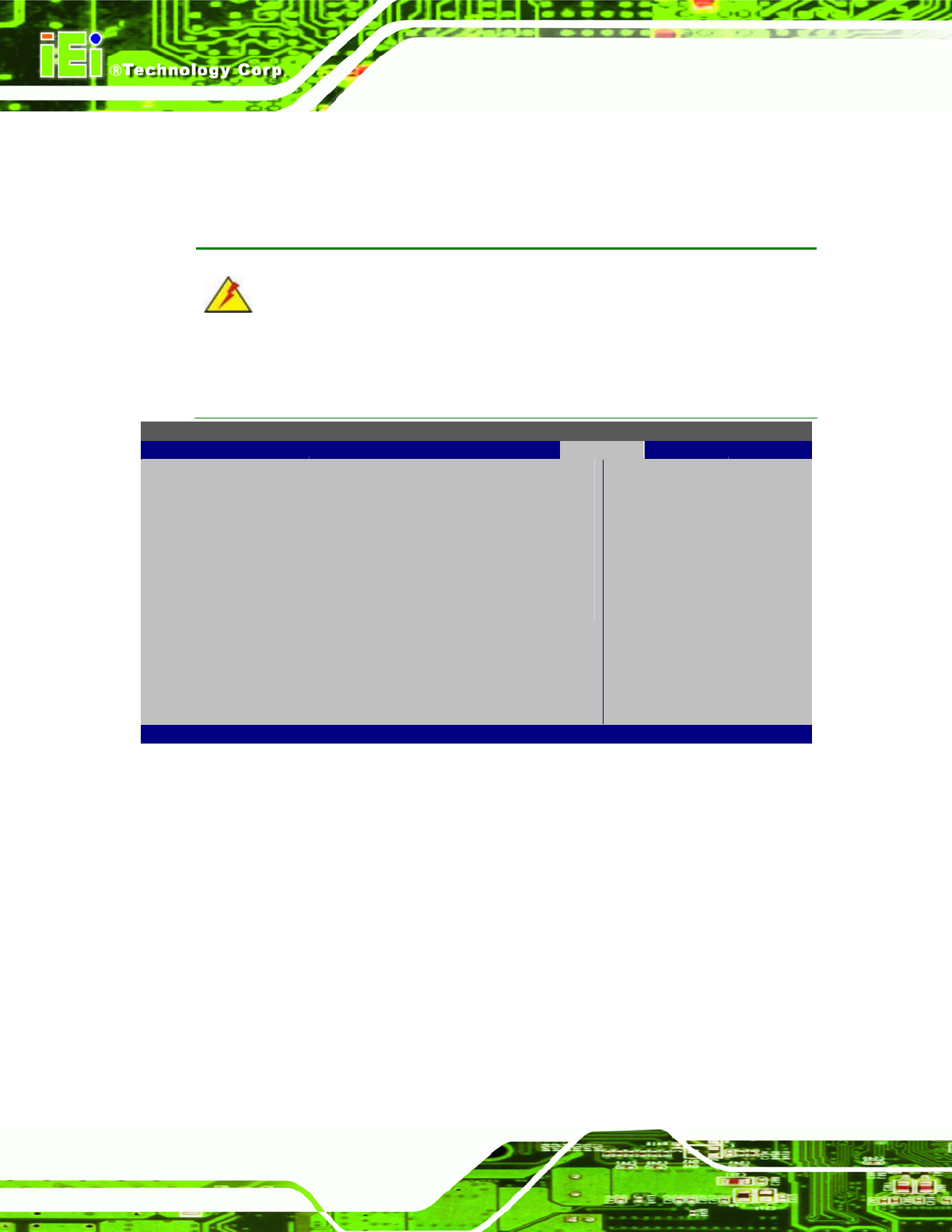
5.7 Chipset
Use the Chipset menu (BIOS Menu 19) to access the NorthBridge and SouthBridge
configuration menus.
WARNING!
Setting the wrong values for the Chipset BIOS selections in the Chipset BIOS
menu may cause the system to malfunction.
BIOS SETUP UTILITY
Main Advanced PCIPnP Boot Security Chipset Exit
Advanced Chipset Settings
⎯⎯⎯⎯⎯⎯⎯⎯⎯⎯⎯⎯⎯⎯⎯⎯⎯⎯⎯⎯⎯⎯⎯⎯⎯⎯⎯⎯⎯⎯⎯
WARNING: Setting wrong values in below section
may cause system to malfunction.
> North Bridge Configuration
> South Bridge Configuration
Configure North Bridge
features
Select Screen
↑ ↓ Select Item
Enter Go to Sub Screen
F1 General Help
F10 Save and Exit
ESC Exit
v02.61 ©Copyright 1985-2006, American Megatrends, Inc.
BIOS Menu 19: Chipset
5.7.1 North Bridge Chipset Configuration
Use the North Bridge Chipset Configuration menu (BIOS Menu 20) to configure the
Northbridge chipset settings.