
User Manual


Table Of Contents
- WAFER-945GSE2
- 1 Introduction
- 2 Packing List
- 3 Connectors
- 3.1 Peripheral Interface Connectors
- 3.2 Internal Peripheral Connectors
- 3.2.1 ATX Power Connector
- 3.2.2 ATX Power Supply Enable Connector
- 3.2.3 Audio Connector (10-pin)
- 3.2.4 Backlight Inverter Connector
- 3.2.5 Battery Connector
- 3.2.6 CompactFlash® Socket
- 3.2.7 Digital Input/Output (DIO) Connector
- 3.2.8 Fan Connector (+12V, 3-pin)
- 3.2.9 Keyboard/Mouse Connector
- 3.2.10 LED Connector
- 3.2.11 LVDS LCD Connector
- 3.2.12 PC/104 Connector
- 3.2.13 PC/104 Power Input Connector
- 3.2.14 Power Button Connector
- 3.2.15 Reset Button Connector
- 3.2.16 SATA Drive Connectors
- 3.2.17 Serial Port Connector, RS-232/422/485
- 3.2.18 SPI Flash Connector
- 3.2.19 USB Connectors (Internal)
- 3.3 External Peripheral Interface Connector Panel
- 4 Installation
- 5 BIOS
- 6 Software Drivers
- A BIOS Options
- B One Key Recovery
- C Terminology
- D Digital I/O Interface
- E Watchdog Timer
- F Hazardous Materials Disclosure
WAFER-945GSE2 3.5" Motherboard
Page 115
Step 7: The program begins to install.
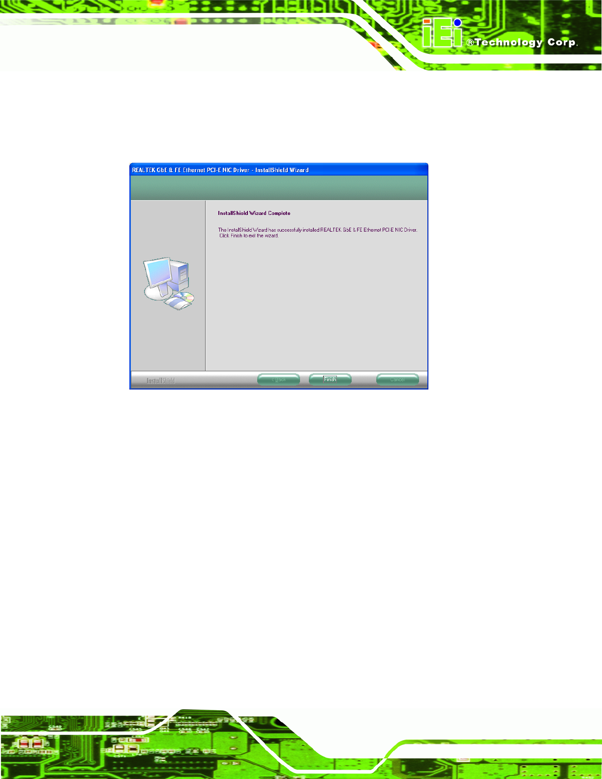
Step 8: When the driver installation is complete, the screen in
Figure 6-18 appears.
Step 9: Click Finish to exit.
Figure 6-18: LAN Driver Installation Complete
6.6 Audio Driver Installation
To install the Audio driver, please do the following.
Step 1: Access the driver list shown in
Figure 6-2. (See Section 6.2)
Step 2: Click “4-Audio”.
Step 3: The installation files are extracted as shown in
Figure 6-19.