
User Manual


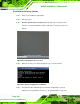


Table Of Contents
- WAFER-945GSE2
- 1 Introduction
- 2 Packing List
- 3 Connectors
- 3.1 Peripheral Interface Connectors
- 3.2 Internal Peripheral Connectors
- 3.2.1 ATX Power Connector
- 3.2.2 ATX Power Supply Enable Connector
- 3.2.3 Audio Connector (10-pin)
- 3.2.4 Backlight Inverter Connector
- 3.2.5 Battery Connector
- 3.2.6 CompactFlash® Socket
- 3.2.7 Digital Input/Output (DIO) Connector
- 3.2.8 Fan Connector (+12V, 3-pin)
- 3.2.9 Keyboard/Mouse Connector
- 3.2.10 LED Connector
- 3.2.11 LVDS LCD Connector
- 3.2.12 PC/104 Connector
- 3.2.13 PC/104 Power Input Connector
- 3.2.14 Power Button Connector
- 3.2.15 Reset Button Connector
- 3.2.16 SATA Drive Connectors
- 3.2.17 Serial Port Connector, RS-232/422/485
- 3.2.18 SPI Flash Connector
- 3.2.19 USB Connectors (Internal)
- 3.3 External Peripheral Interface Connector Panel
- 4 Installation
- 5 BIOS
- 6 Software Drivers
- A BIOS Options
- B One Key Recovery
- C Terminology
- D Digital I/O Interface
- E Watchdog Timer
- F Hazardous Materials Disclosure
WAFER-945GSE2 3.5" Motherboard
Page 134
Figure B-14: Select a Local Source Drive
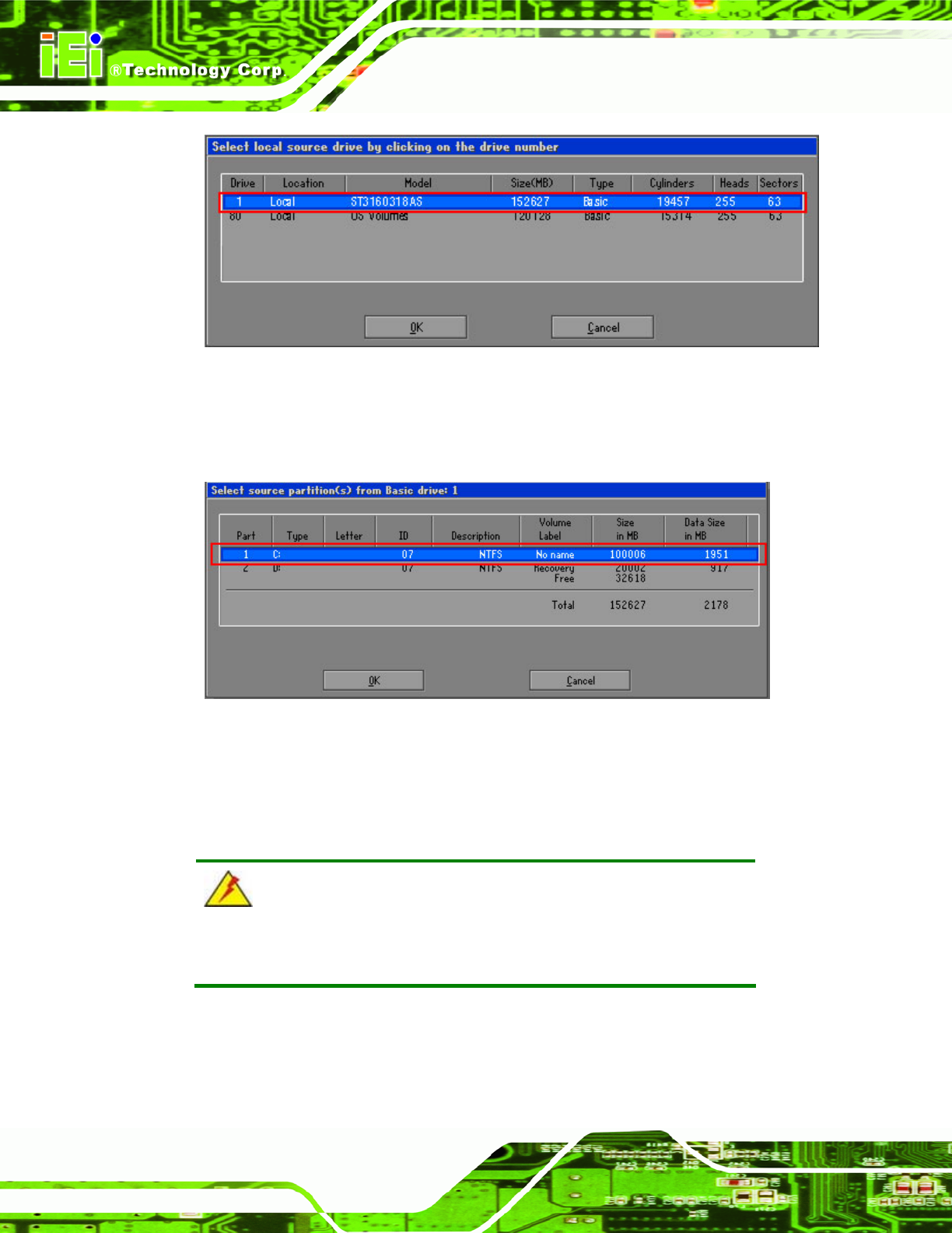
Step 6: Select a source partition (Part 1) from basic drive as shown in
78Figure B-15.
Then click OK.
Figure B-15: Select a Source Partition from Basic Drive
Step 7: Select 1.2: [Recovery] NTFS drive and enter a file name called iei
(
78Figure B-16). Click Save. The factory default image will then be saved in the
selected recovery drive and named IEI.GHO.
WARNING:
The file name of the factory default image must be iei.GHO.