
User Manual


Table Of Contents
- WAFER-945GSE2
- 1 Introduction
- 2 Packing List
- 3 Connectors
- 3.1 Peripheral Interface Connectors
- 3.2 Internal Peripheral Connectors
- 3.2.1 ATX Power Connector
- 3.2.2 ATX Power Supply Enable Connector
- 3.2.3 Audio Connector (10-pin)
- 3.2.4 Backlight Inverter Connector
- 3.2.5 Battery Connector
- 3.2.6 CompactFlash® Socket
- 3.2.7 Digital Input/Output (DIO) Connector
- 3.2.8 Fan Connector (+12V, 3-pin)
- 3.2.9 Keyboard/Mouse Connector
- 3.2.10 LED Connector
- 3.2.11 LVDS LCD Connector
- 3.2.12 PC/104 Connector
- 3.2.13 PC/104 Power Input Connector
- 3.2.14 Power Button Connector
- 3.2.15 Reset Button Connector
- 3.2.16 SATA Drive Connectors
- 3.2.17 Serial Port Connector, RS-232/422/485
- 3.2.18 SPI Flash Connector
- 3.2.19 USB Connectors (Internal)
- 3.3 External Peripheral Interface Connector Panel
- 4 Installation
- 5 BIOS
- 6 Software Drivers
- A BIOS Options
- B One Key Recovery
- C Terminology
- D Digital I/O Interface
- E Watchdog Timer
- F Hazardous Materials Disclosure
WAFER-945GSE2 3.5" Motherboard
Page 141
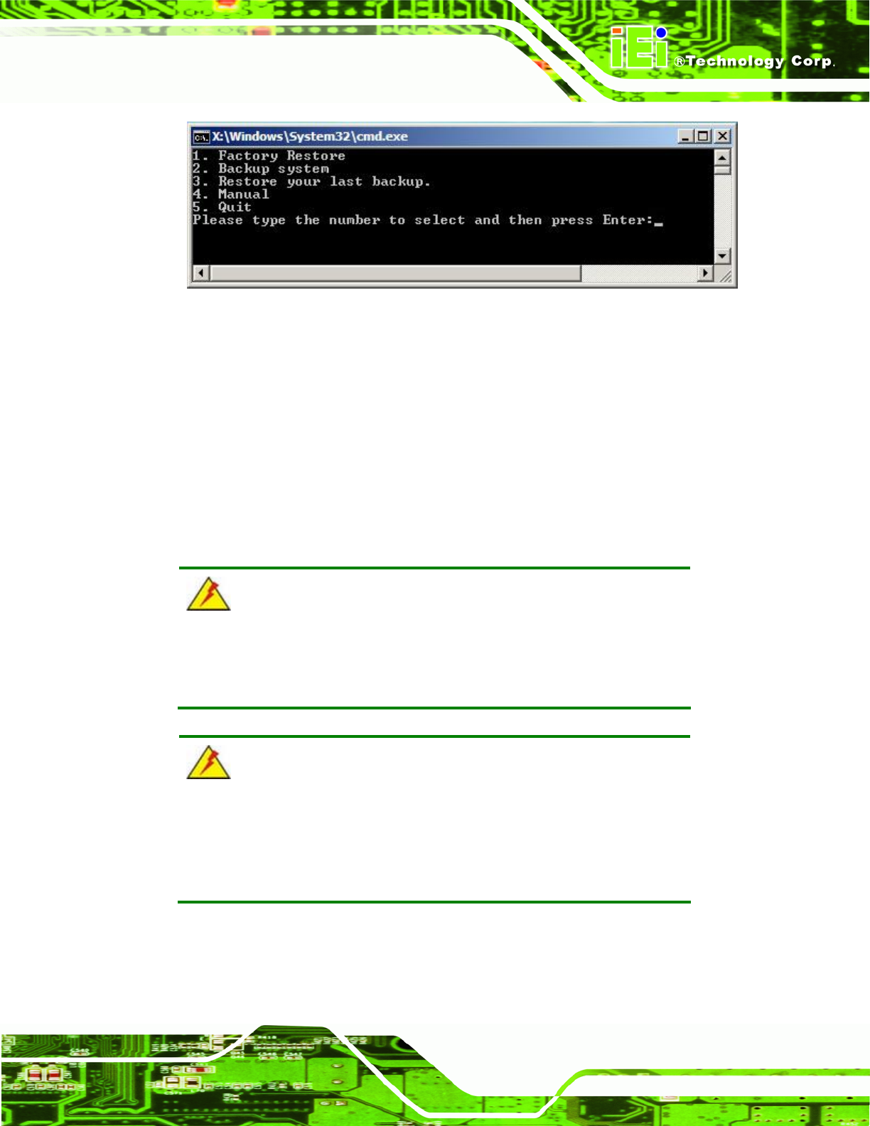
Figure B-26: Recovery Tool Main Menu
The recovery tool has several functions including:
1. Factory Restore: Restore the factory default image (iei.GHO) created in
Section
78B.2.5.
2. Backup system: Create a system backup image (iei_user.GHO) which will be
saved in the hidden partition.
3. Restore your last backup: Restore the last system backup image
4. Manual: Enter the Symantec Ghost window to configure manually.
5. Quit: Exit the recovery tool and restart the system.
WARNING:
Please do not turn off the system power during the process of system
recovery or backup.
WARNING:
All data in the system will be deleted during the system recovery.
Please backup the system files before restoring the system (either
Factory Restore or Restore Backup).