
User Manual


Table Of Contents
- WAFER-945GSE2
- 1 Introduction
- 2 Packing List
- 3 Connectors
- 3.1 Peripheral Interface Connectors
- 3.2 Internal Peripheral Connectors
- 3.2.1 ATX Power Connector
- 3.2.2 ATX Power Supply Enable Connector
- 3.2.3 Audio Connector (10-pin)
- 3.2.4 Backlight Inverter Connector
- 3.2.5 Battery Connector
- 3.2.6 CompactFlash® Socket
- 3.2.7 Digital Input/Output (DIO) Connector
- 3.2.8 Fan Connector (+12V, 3-pin)
- 3.2.9 Keyboard/Mouse Connector
- 3.2.10 LED Connector
- 3.2.11 LVDS LCD Connector
- 3.2.12 PC/104 Connector
- 3.2.13 PC/104 Power Input Connector
- 3.2.14 Power Button Connector
- 3.2.15 Reset Button Connector
- 3.2.16 SATA Drive Connectors
- 3.2.17 Serial Port Connector, RS-232/422/485
- 3.2.18 SPI Flash Connector
- 3.2.19 USB Connectors (Internal)
- 3.3 External Peripheral Interface Connector Panel
- 4 Installation
- 5 BIOS
- 6 Software Drivers
- A BIOS Options
- B One Key Recovery
- C Terminology
- D Digital I/O Interface
- E Watchdog Timer
- F Hazardous Materials Disclosure
WAFER-945GSE2 3.5" Motherboard
Page 146
B.5 Other Information
B.5.1 Using AHCI Mode or ALi M5283 / VIA VT6421A Controller
When the system uses AHCI mode or some specific SATA controllers such as ALi M5283
or VIA VT6421A, the SATA RAID/AHCI driver must be installed before using one key
recovery. Please follow the steps below to install the SATA RAID/AHCI driver.
Step 1: Copy the SATA RAID/AHCI driver to a floppy disk and insert the floppy disk into
a USB floppy disk drive. The SATA RAID/AHCI driver must be especially
designed for the on-board SATA controller.
Step 2: Connect the USB floppy disk drive to the system.
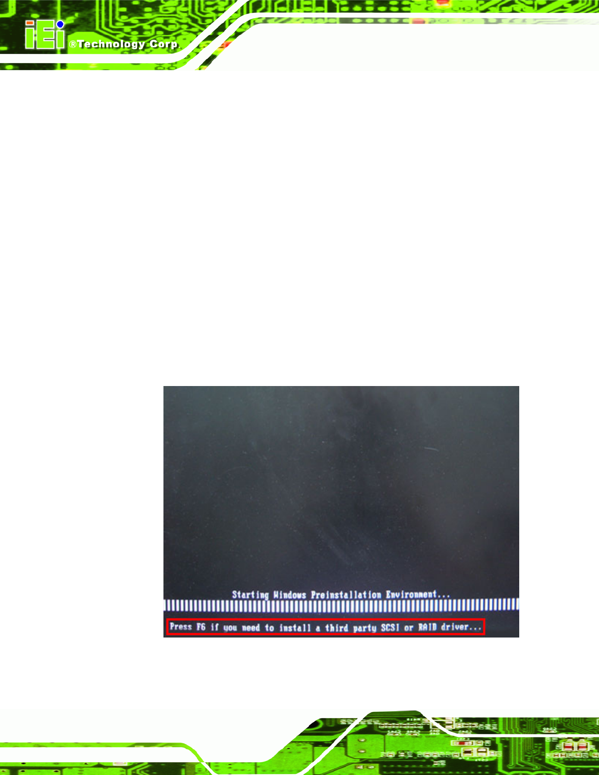
Step 3: Insert the One Key Recovery CD into the system and boot the system from the
CD.
Step 4: When launching the recovery tool, press <F6>.