
User Manual


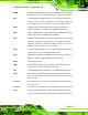


Table Of Contents
- WAFER-945GSE2
- 1 Introduction
- 2 Packing List
- 3 Connectors
- 3.1 Peripheral Interface Connectors
- 3.2 Internal Peripheral Connectors
- 3.2.1 ATX Power Connector
- 3.2.2 ATX Power Supply Enable Connector
- 3.2.3 Audio Connector (10-pin)
- 3.2.4 Backlight Inverter Connector
- 3.2.5 Battery Connector
- 3.2.6 CompactFlash® Socket
- 3.2.7 Digital Input/Output (DIO) Connector
- 3.2.8 Fan Connector (+12V, 3-pin)
- 3.2.9 Keyboard/Mouse Connector
- 3.2.10 LED Connector
- 3.2.11 LVDS LCD Connector
- 3.2.12 PC/104 Connector
- 3.2.13 PC/104 Power Input Connector
- 3.2.14 Power Button Connector
- 3.2.15 Reset Button Connector
- 3.2.16 SATA Drive Connectors
- 3.2.17 Serial Port Connector, RS-232/422/485
- 3.2.18 SPI Flash Connector
- 3.2.19 USB Connectors (Internal)
- 3.3 External Peripheral Interface Connector Panel
- 4 Installation
- 5 BIOS
- 6 Software Drivers
- A BIOS Options
- B One Key Recovery
- C Terminology
- D Digital I/O Interface
- E Watchdog Timer
- F Hazardous Materials Disclosure
WAFER-945GSE2 3.5" Motherboard
Page 154
D.1 Introduction
The DIO connector on the WAFER-945GSE2 is interfaced to GPIO ports on the Super I/O
chipset. The DIO has both 4-bit digital inputs and 4-bit digital outputs. The digital inputs
and digital outputs are generally control signals that control the on/off circuit of external
devices or TTL devices. Data can be read or written to the selected address to enable the
DIO functions.
NOTE:
For further information, please refer to the datasheet for the Super I/O
chipset.
D.2 DIO Connector Pinouts
Pin Description Super I/O Pin Super I/O Pin Description
1 Ground N/A N/A
2 VCC N/A N/A
3 Output 3 GP23 General Purpose I/O Port 2 Bit 3
4 Output 2 GP22 General Purpose I/O Port 2 Bit 2
5 Output 1 GP21 General Purpose I/O Port 2 Bit 1
6 Output 0 GP20 General Purpose I/O Port 2 Bit 0
7 Input 3 GP33 General Purpose I/O 33
8 Input 2 GP32 General Purpose I/O 32
9 Input 1 GP31 General Purpose I/O 31
10 Input 0 GP30 General Purpose I/O 30
D.3 Assembly Language Samples
D.3.1 Enable the DIO Input Function
The BIOS interrupt call INT 15H controls the digital I/O. An assembly program to enable
digital I/O input functions is listed below.
MOV AX, 6F08H
Sets the digital port as input