
User Manual


Table Of Contents
- WAFER-945GSE2
- 1 Introduction
- 2 Packing List
- 3 Connectors
- 3.1 Peripheral Interface Connectors
- 3.2 Internal Peripheral Connectors
- 3.2.1 ATX Power Connector
- 3.2.2 ATX Power Supply Enable Connector
- 3.2.3 Audio Connector (10-pin)
- 3.2.4 Backlight Inverter Connector
- 3.2.5 Battery Connector
- 3.2.6 CompactFlash® Socket
- 3.2.7 Digital Input/Output (DIO) Connector
- 3.2.8 Fan Connector (+12V, 3-pin)
- 3.2.9 Keyboard/Mouse Connector
- 3.2.10 LED Connector
- 3.2.11 LVDS LCD Connector
- 3.2.12 PC/104 Connector
- 3.2.13 PC/104 Power Input Connector
- 3.2.14 Power Button Connector
- 3.2.15 Reset Button Connector
- 3.2.16 SATA Drive Connectors
- 3.2.17 Serial Port Connector, RS-232/422/485
- 3.2.18 SPI Flash Connector
- 3.2.19 USB Connectors (Internal)
- 3.3 External Peripheral Interface Connector Panel
- 4 Installation
- 5 BIOS
- 6 Software Drivers
- A BIOS Options
- B One Key Recovery
- C Terminology
- D Digital I/O Interface
- E Watchdog Timer
- F Hazardous Materials Disclosure
WAFER-945GSE2 3.5" Motherboard
Page 9
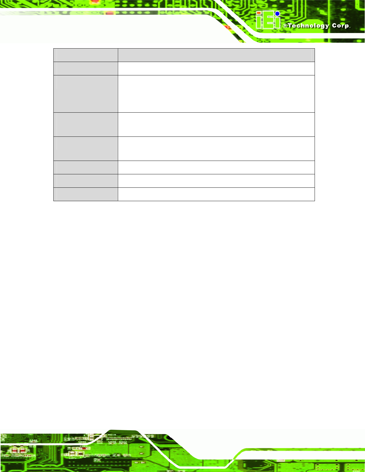
Specification/Model WAFER-945GSE2
Watchdog Timer
Software programmable supports 1~255 sec. system reset
Power Supply
5 V only
12 V for LCD/system fan
AT and ATX support
Power
Consumption
5V @ 3.1 A (1.6 GHz Intel® Atom™ N270 with on-board 1.0 GB DDR2
SDRAM)
Temperature
0ºC ~ 60ºC (WAFER-945GSE2-N270-R20)
-20ºC ~ 70ºC (WAFER-945GSE2-N270W-R20)
Humidity (operating)
5% ~ 95% (non-condensing)
Dimensions (LxW)
146 mm x 102 mm
Weight (GW/NW)
700 g/230 g
Table 1-2: WAFER-945GSE2 Specifications