
User Manual


Table Of Contents
- WAFER-945GSE2
- 1 Introduction
- 2 Packing List
- 3 Connectors
- 3.1 Peripheral Interface Connectors
- 3.2 Internal Peripheral Connectors
- 3.2.1 ATX Power Connector
- 3.2.2 ATX Power Supply Enable Connector
- 3.2.3 Audio Connector (10-pin)
- 3.2.4 Backlight Inverter Connector
- 3.2.5 Battery Connector
- 3.2.6 CompactFlash® Socket
- 3.2.7 Digital Input/Output (DIO) Connector
- 3.2.8 Fan Connector (+12V, 3-pin)
- 3.2.9 Keyboard/Mouse Connector
- 3.2.10 LED Connector
- 3.2.11 LVDS LCD Connector
- 3.2.12 PC/104 Connector
- 3.2.13 PC/104 Power Input Connector
- 3.2.14 Power Button Connector
- 3.2.15 Reset Button Connector
- 3.2.16 SATA Drive Connectors
- 3.2.17 Serial Port Connector, RS-232/422/485
- 3.2.18 SPI Flash Connector
- 3.2.19 USB Connectors (Internal)
- 3.3 External Peripheral Interface Connector Panel
- 4 Installation
- 5 BIOS
- 6 Software Drivers
- A BIOS Options
- B One Key Recovery
- C Terminology
- D Digital I/O Interface
- E Watchdog Timer
- F Hazardous Materials Disclosure
WAFER-945GSE2 3.5" Motherboard
Page 33
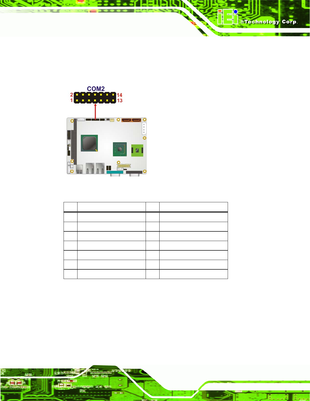
The 14-pin serial port connector connects to the COM2 serial communications channels.
COM2 is a multi function channel. In default mode COM2 is an RS-232 serial
communication channel but, with the COM2 function select jumper, can be configured as
either an RS-422 or RS-485 serial communications channel.
Figure 3-19: RS-232/422/485 Serial Port Connector Location
Pin Description Pin
Description
1 DATA CARRIER DETECT (DCD)
2 DATA SET READY (DSR)
3 RECEIVE DATA (RXD) 4 REQUEST TO SEND (RTS)
5 TRANSMIT DATA (TXD) 6 CLEAR TO SEND (CTS)
7 DATA TERMINAL READY (DTR)
8 RING INDICATOR (RI)
9 GND 10 N/C
11 TXD485+ 12 TXD485#
13 RXD485+ 14 RXD485#
Table 3-20: RS-232/422/485 Serial Port Connector Pinouts
3.2.18 SPI Flash Connector
CN Label: JSPI1
CN Type:
8-pin header
CN Location:
See
Figure 3-20
CN Pinouts:
See
Table 3-21