
User Manual


Table Of Contents
- WAFER-945GSE2
- 1 Introduction
- 2 Packing List
- 3 Connectors
- 3.1 Peripheral Interface Connectors
- 3.2 Internal Peripheral Connectors
- 3.2.1 ATX Power Connector
- 3.2.2 ATX Power Supply Enable Connector
- 3.2.3 Audio Connector (10-pin)
- 3.2.4 Backlight Inverter Connector
- 3.2.5 Battery Connector
- 3.2.6 CompactFlash® Socket
- 3.2.7 Digital Input/Output (DIO) Connector
- 3.2.8 Fan Connector (+12V, 3-pin)
- 3.2.9 Keyboard/Mouse Connector
- 3.2.10 LED Connector
- 3.2.11 LVDS LCD Connector
- 3.2.12 PC/104 Connector
- 3.2.13 PC/104 Power Input Connector
- 3.2.14 Power Button Connector
- 3.2.15 Reset Button Connector
- 3.2.16 SATA Drive Connectors
- 3.2.17 Serial Port Connector, RS-232/422/485
- 3.2.18 SPI Flash Connector
- 3.2.19 USB Connectors (Internal)
- 3.3 External Peripheral Interface Connector Panel
- 4 Installation
- 5 BIOS
- 6 Software Drivers
- A BIOS Options
- B One Key Recovery
- C Terminology
- D Digital I/O Interface
- E Watchdog Timer
- F Hazardous Materials Disclosure
WAFER-945GSE2 3.5" Motherboard
Page 55
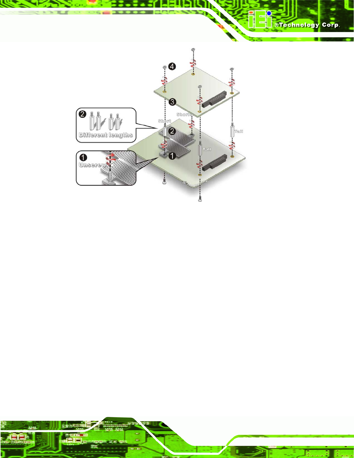
Figure 4-12: WAFER-945GSE2 PC/104 module installation
Step 4: Remove retention nuts. Remove the two nuts securing the heatsink and two
nuts securing the WAFER-945GSE2 to the chassis.
Step 5: Attach intermediate poles. Insert the two short plastic intermediate poles into
the bolts securing the heatsink. Insert the two tall plastic intermediate poles.
Step 6: Align the PC/104 connector. Align the PC/104 module connector with the
corresponding connector on the WAFER-945GSE2 (connector CN2). Gently
push the module down to ensure the connectors are properly connected.
Step 7: Replace the retention nuts. Screw the four retention nuts onto the
intermediate poles to secure the PC/104 module.
4.6.6 USB Cable (Dual Port without Bracket) (Optional)
The WAFER-945GSE2 is shipped with a dual port USB 2.0 cable. To connect the USB
cable connector, please follow the steps below.