
User Manual


Table Of Contents
- WAFER-945GSE2
- 1 Introduction
- 2 Packing List
- 3 Connectors
- 3.1 Peripheral Interface Connectors
- 3.2 Internal Peripheral Connectors
- 3.2.1 ATX Power Connector
- 3.2.2 ATX Power Supply Enable Connector
- 3.2.3 Audio Connector (10-pin)
- 3.2.4 Backlight Inverter Connector
- 3.2.5 Battery Connector
- 3.2.6 CompactFlash® Socket
- 3.2.7 Digital Input/Output (DIO) Connector
- 3.2.8 Fan Connector (+12V, 3-pin)
- 3.2.9 Keyboard/Mouse Connector
- 3.2.10 LED Connector
- 3.2.11 LVDS LCD Connector
- 3.2.12 PC/104 Connector
- 3.2.13 PC/104 Power Input Connector
- 3.2.14 Power Button Connector
- 3.2.15 Reset Button Connector
- 3.2.16 SATA Drive Connectors
- 3.2.17 Serial Port Connector, RS-232/422/485
- 3.2.18 SPI Flash Connector
- 3.2.19 USB Connectors (Internal)
- 3.3 External Peripheral Interface Connector Panel
- 4 Installation
- 5 BIOS
- 6 Software Drivers
- A BIOS Options
- B One Key Recovery
- C Terminology
- D Digital I/O Interface
- E Watchdog Timer
- F Hazardous Materials Disclosure
WAFER-945GSE2 3.5" Motherboard
Page 78
o CPU Temperature
o System Temperature
Fan Speed: The CPU cooling fan speed is monitored.
o CPU Fan Speed
Voltages: The following system voltages are monitored
o CPU Core
o +1.05V
o +3.30V
o +5.00V
o +12.0 V
o +1.5V
o +1.8V
o 5VSB
o VBAT
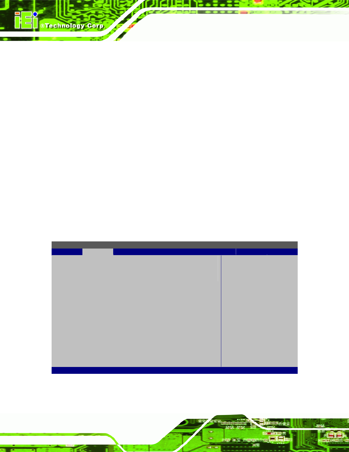
5.3.5 Power Configuration
The Power Configuration menu (BIOS Menu 8) configures the Advanced Configuration
and Power Interface (ACPI) and Power Management (APM) options.
BIOS SETUP UTILITY
Advanced
Select AT/ATX Power [BY HARDWARE]
Auto Power Button Status [Enabled]
Default set AUTO is
detect power supply
status.
If set AT Power, Power
State will Auto set Power
On.
Select Screen
↑ ↓ Select Item
+ - Change Option
F1 General Help
F10 Save and Exit
ESC Exit
v02.61 ©Copyright 1985-2006, American Megatrends, Inc.
BIOS Menu 8: Power Configuration