
User's Manual


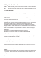


Table Of Contents

8
5 Connections and displays
The illustration below shows a DTE800 standard reader with all its connection options� Details of the con-
nections and the pin assignments of plugs and sockets are provided in the following pages�
Figure: General view of the DTE
1: Communication connection: M12
2: Status indicators: 2 coloured LEDs (red, green)
3: Power supply connection: M12 male, 4-pin, A-coded
4: GPIO connection 1: M12 female, 5-pin, A-coded
5: GPIO connection 2: M12 female, 5-pin, A-coded
6: Antenna connection 1: R-TNC 50 Ohm
7: Antenna connection 2: R-TNC 50 Ohm
8: Antenna connection 3: R-TNC 50 Ohm
9: Antenna connection 4: R-TNC 50 Ohm