
User's Manual


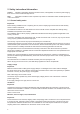


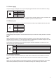

Table Of Contents

9
UK
5.1 Power supply
The power supply is arranged as a four-pin round-pin plug with and M12 connection thread in A-coding�
4
2 1
3
Pin Assignment
1 + 24 V DC
2
3 GND
4
Only power supply units with power limitation are approved for operation with the device� This means that
the secondary side of the power supply unit is limited to a power of maximum 100 W�
5.2 Ethernet port
This data interface is arranged as a 4-pin M12 socket with D-coding� Only shielded cables may be used�
3
1 2
4
Pin Assignment
1 TD +
2 RD +
3 TD -
4 RD -
5.3 Digital inputs and outputs
The digital inputs and outputs are communicated via two five-pin sockets in A-coding with M12 connection
threads�
Note
Please note that the load per channel is limited to a maximum of 0�5 A, and the total load across all the
channels must not exceed 1�5 A� The inputs and outputs are designed for a maximum voltage of 30 V DC�
Further information can be found in the data sheet for the reader�
The activation and evaluation can be performed using the software ReaderStart v2, with the DLL sup-
plied, or by access to the reader protocol�
3
1 2
4
5
Pin Assignment
1 VCC
2 Input
3 GND
4 Output
5 not connected
5.4 Antenna Connection
For the connection to the RFID antennas, the reader has four antenna connections that are of reverse
TNC design� Please only use the cable from the accessories or equivalent cable for this connection�
Note
Please only use cable suitable for the impedance (50 Ohm), as otherwise the performance of the reader
will be severely limited by the mismatch� If the mismatch is large, the reader may indicate a fault�