Installation Instructions RF-identification system Read/write head 80231611 / 00 09 / 2015 DTM424 DTM425 DTM426 DTM427 UK
Content 1 Preliminary note ���������������������������������������������������������������������������������������������������4 1.1 Symbols used �����������������������������������������������������������������������������������������������4 1.2 Warnings used ����������������������������������������������������������������������������������������������4 2 Safety instructions �����������������������������������������������������������������������������������������������4 2.
9 Dimensions ��������������������������������������������������������������������������������������������������������13 10 Technical data ��������������������������������������������������������������������������������������������������13 11 Maintenance, repair and disposal ��������������������������������������������������������������������14 12 Approvals/standards ����������������������������������������������������������������������������������������14 12.
1 Preliminary note This document is part of the device and contains information about the correct handling of the product. This document is intended for specialists. These specialists are people who are qualified by their training and their experience to see risks and to avoid possible hazards that may be caused during operation or maintenance of the device. Read this document before use to familiarise yourself with operating conditions, installation and operation.
In case of malfunction of the device or uncertainties please contact the manufacturer. Any tampering with the device can seriously affect the safety of operators and machinery. This is not permitted and leads to an exclusion of liability and warranty. 2.2 Radio equipment In general, radio equipment must not be used in the vicinity of petrol stations, fuel depots, chemical plants or blasting operations. ►► Do not transport and store any flammable gases, liquids or explosive substances near the unit. UK 2.
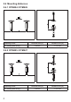
4.2 Overview Art. no.: Function: DTM424 / DTM426 read/write head Operating frequency: RFID standard: Type: 13.56 Mhz ISO15693 M18, flush mountable Art. no.: Function: DTM425 / DTM427 read/write head Operating frequency: RFID standard: Type: 13.56 Mhz ISO15693 M18, non flush mountable 5 Installation 5.1 General installation instructions When mounting several read/write heads adhere to the minimum distances between the systems.
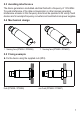
5.3 Avoiding interference The device generates a modulated electrical field with a frequency of 13.56 MHz. To avoid interference of the data communication no other devices generating interference emission in this frequency band must be operated in its vicinity. Such devices are for example frequency converters and switched-mode power supplies. 5.4 Mechanical design UK 1: Sensing face (DTM424 / DTM426) 1: Sensing face (DTM425 / DTM427) 5.5 Fixing example ►► Fix the device using the supplied nuts (M18).
5.6 Mounting distances 5.6.1 DTM424 / DTM426 Operating mode For reading and writing Distance side (A) ≥ 50 mm Distance front (B) ≥ 100 mm Distance side (A) ≥ 65 mm Distance front (B) ≥ 180 mm 5.6.
5.7 Positioning of the ID tags A selection of ID tags is available on our website at: www.ifm.com → Product line → Identification systems → Tags 5.7.1 DTM424 / DTM426 D UK ►► Align the ID tag on the antenna central axis. ID tag Distance read/write head (D) Plastics Type E80371 18 mm All indications apply to static read/write operations. 5.7.2 DTM425 / DTM427 D ►► Align the ID tag on the antenna central axis.
6 Electrical connection ATTENTION The unit must be connected by a qualified electrician. Device of protection class III (PC III) The electric supply must only be made via PELV/SELV circuits. ►► Disconnect power before connecting the unit. 6.1 Wiring The device has a 5-pole round M12 connector (A-coded). The pin connection corresponds to CiA DR-303-1.
7 Indicators 7.1 DTM424 / DTM425 (CANopen) LED UK LED DTM424 (flush) DTM425 (non flush) Operating status LED red LED green LED yellow Preoperational Off Lights permanently Off Preoperational and tag detected Off Flashes alternately with yellow LED (every 1.6 s) Flashes alternately with green LED (every 1.6 s) Operational Off Flashes (every 0.4 s) Off Operational and tag detected Off Off Lights permanently Configuration error Flashes (every 0.
7.
8 Operation The device is operated in a CANopen network. The CAN network must be correctly configured so that the device functions reliably. Depending on the configuration of the CAN network the settings under (→ 8.1) and (→ 8.2) have to be adapted. More notes on operation can be found in the operating instructions: Original Scale Drawing (MTD) www.ifm.com → Data sheet search → DTM425 → Operating instructions P_MZ_190_0017 UK DTM425 8.
11 Maintenance, repair and disposal ►► Do not open the housing as the device does not contain any components which can be maintained by the user. The device must only be repaired by the manufacturer. ►► Dispose of the device in accordance with the national environmental regulations. 12 Approvals/standards 12.1 Radio approvals 12.1.1 Overview The overview of the approval status of a unit is available on our website at: www.ifm.com → Data sheet search → e.g. DTM424 → More information 12.1.
12.1.4 Canada IC note: This device complies with Industry Canada license-exempt RSS standards. Operation is subject to the following two conditions: 1. The device may not cause interference, and 2. the user of the device must accept any interference received, including interference that may cause undesired operation. 12.1.