Installation Instructions RF-identification system Read/write head 706097/ 07 09 / 2011 ANT512 UK
Contents 1 Preliminary note ...................................................................................................4 1.1 Symbols used ...............................................................................................4 2 Safety instructions ...............................................................................................4 2.1 General .........................................................................................................4 2.2 Radio equipment ...........
12.1.1 Overview...........................................................................................12 12.1.2 Europe ..............................................................................................12 12.1.3 Notices FCC .....................................................................................12 12.2 EC declaration of conformity ....................................................................
1 Preliminary note This document is part of the device and contains information about the correct handling of the product. This document is intended for specialists. These specialists are people who are qualified by their training and their experience to see risks and to avoid possible hazards that may be caused during operation or maintenance of the device. Read this document before use to familiarise yourself with operating conditions, installation and operation.
2.2 Radio equipment In general, radio equipment must not be used in the vicinity of petrol stations, fuel depots, chemical plants or blasting operations. ► Do not transport and store any flammable gases, liquids or explosive substances near the unit. 2.3 Interference of electronic and medical devices Operation can affect the function of electronic devices that are not correctly shielded. ► Disconnect the device in the vicinity of medical equipment.
4.2 Overview Art. no.: Function: Type designation: Operating frequency: H X W X D [mm]: ANT512 Read/write head DTRLF MCRWIDUS01 125 kHz 40 x 40 x 54 5 Installation 5.1 General installation instructions When mounting several read/write heads adhere to the minimum distances between the systems. Flush mounting of a read/write head in metal reduces the read/write distance.
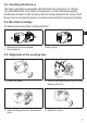
5.3 Avoiding interference The device generates a modulated electrical field with a frequency of 125 kHz. To avoid interference of the data communication no other devices generating interference emission in this frequency band must be operated in its vicinity. Such devices are for example frequency converters and switched-mode power supplies. 5.4 Mechanical design On delivery the sensing face is facing the front. UK 1 2 1: Antenna head (can be aligned) 2: Fixing element Factory setting 5.
5.6 Fixing ► The device is fixed with 2 M5 screws and nuts. Order non flush or flush. non flush flush 5.
5.8 Positioning of the ID tags 1 E80360 E80361 UK 1: front side 5.9 Orientation of the ID tags 2 1 2 1: antenna axis ATN512 = ID tag axis 2: middle of the antenna ATN512 = middle of the ID tag 5.10 Read/write distances ID tag Type Installation read/write head Read Write E80360 60 55 E80361 60 55 All indications apply to static read/write operations. If not otherwise stated they refer to ID tag installation in a non-metallic environment.
6 Electrical connection 6.1 Wiring ► Connect the device to the evaluation unit DTE10x using the M12 connection. Voltage is supplied via the evaluation unit. 2 1 1 4 3 4 3 L+ DATA L A selection of sockets is available on our website at: www.ifm.com → data sheet search → ANT512 → Accessories Cables with the following characteristics are suitable for the connection: Length 20 m Ohmic resistance (feed + return line) max. 3Ω Effective cable capacity max. 3 nF 6.
LED green yellow green + yellow Status ON OFF FLASHING SLOWLY ON (permanently) ON (pulse) FLASHING QUICKLY OFF FLASHING ALTERNATELY Description operating voltage OK operating voltage missing deactivated ID tag detected ID tag read/written successfully error when reading/writing on ID tag no ID tag in the field or faulty ID tag in the field or invalid ID tag in the field UK error in communication or device fault 8 Operation The read/write head is configured via the connected evaluation unit DTE10x.
10 Technical data The data sheets are available on our website at: www.ifm.com → data sheet search → ANT512 11 Maintenance, repair and disposal ► Do not open the housing as the device does not contain any components which must be maintained by the user. The device must only be repaired by the manufacturer. ► Dispose of the device in accordance with the national environmental regulations. 12 Approvals/standards 12.1 Radio approvals 12.1.