
Operating Instructions

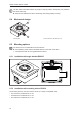
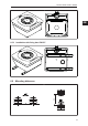
Table Of Contents
- Contents
- 1 Preliminary note
- 2 Safety instructions
- 3 Intended use
- 4 Items supplied
- 5 Function
- 5.1 Device overview
- 5.2 IO-Link
- 5.2.1 General information
- 5.2.2 Device-specific information
- 5.2.3 Device-specific parameters
- 5.2.3.1 Parameter “Data Hold Time”
- 5.2.3.2 Parameter "Auto-Read/Write Address"
- 5.2.3.3 Parameter "Auto-Read/WriteData Length"
- 5.2.3.4 Parameter "ID Tag Memory Area for Auto-Read/Write"
- 5.2.3.5 Parameter “ID Tag Access Password"
- 5.2.3.6 Parameter "ID Tag Selection Target
- 5.2.3.7 Parameter "ID Tag Selection Mask”
- 5.2.3.8 Parameter "ID Tag Selection Start Bit”
- 5.2.3.9 Parameter "ID Tag Selection Length”
- 5.2.3.10 Parameter "RSSI Filter Lowest Value”
- 5.2.3.11 Parameter "RSSI Filter Highest Value”
- 5.2.3.12 Parameter "Activate RSSI Filter”
- 5.2.3.13 Parameter “Antenna Output Power for Read Access"
- 5.2.3.14 Parameter “Antenna Output Power for Write Access"
- 5.2.3.15 Parameter "ID Tag Detection Mode”
- 5.3 ID tag
- 6 Mounting
- 7 Electrical connection
- 8 Operating and display elements
- 9 Operation
- 9.1 Status bits
- 9.2 Operating mode "SINGLE EPC
- 9.3 Operating Mode “READ DATA AUTO"
- 9.4 Operating Mode “WRITE DATA AUTO"
- 9.5 Operating mode "EPC REPORT
- 9.6 Operating mode "EPC LIST
- 9.7 Operating mode "WRITE EPC”
- 9.8 Operating mode "READ DATA
- 9.9 Operating mode "WRITE DATA”
- 9.10 Operating mode "LOCK DATA”
- 9.11 Error values when executing commands
- 10 Maintenance, repair and disposal
- 11 Approvals / standards
- Glossary

DTI801 DTI901 DTI911 DTI961
17
6 Mounting
ATTENTION
Radiated electromagnetic field strengths
w The device sends ultrahigh frequency electromagnetic waves. It complies with the
country-specific limit values for the public and workers.
u Disconnect the device in the vicinity of medical equipment.
6.1 Installation instructions for devices
Devices installed next to each other interfere if they are not configured correspondingly.
When installing several compact RFID devices adhere to the minimum distances between the
systems.
Installing a device in or on metal reduces the read and write distance.
Device performance can be affected if positioned in the immediate vicinity of powerful HF
emission sources such as welding transformers.
6.2 Installation instructions for ID tags
For installation in and on metal the ID tags provided for this purpose must be used.
The ID tag must be positioned in the area of the sensing face. (Ò Mechanical design/18)
When doing so, the angle of aperture and the operating distance must be adhered to (→ Data
sheet of the device).
The orientation of the compact RFID device axis must correspond with the axis of the ID tag.
6.3 Avoiding interference
The device generates a modulated electromagnetic field in the following frequency ranges:
DTI801: 865-868MHz
DTI901: 902-928MHz
DTI911: 920–925 MHz
DTI961: 916.8–920.4 MHz
Interference in data communication is avoided if there are no other RFID UHF devices in the vicinity. If
there are other RFID UHF devices in the vicinity:
u The mounting distances between the devices should be as large as possible. (Ò Mounting
distances/19)
u Use the RSSI filter. (Ò Parameter "Activate RSSI Filter”/13)
u Use the devices in alternating operation.
u Switch the HF field of the device on/off.
GB