
Operating Instructions

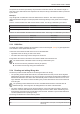
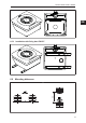
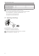
Table Of Contents
- Contents
- 1 Preliminary note
- 2 Safety instructions
- 3 Intended use
- 4 Items supplied
- 5 Function
- 5.1 Device overview
- 5.2 IO-Link
- 5.2.1 General information
- 5.2.2 Device-specific information
- 5.2.3 Device-specific parameters
- 5.2.3.1 Parameter “Data Hold Time”
- 5.2.3.2 Parameter "Auto-Read/Write Address"
- 5.2.3.3 Parameter "Auto-Read/WriteData Length"
- 5.2.3.4 Parameter "ID Tag Memory Area for Auto-Read/Write"
- 5.2.3.5 Parameter “ID Tag Access Password"
- 5.2.3.6 Parameter "ID Tag Selection Target
- 5.2.3.7 Parameter "ID Tag Selection Mask”
- 5.2.3.8 Parameter "ID Tag Selection Start Bit”
- 5.2.3.9 Parameter "ID Tag Selection Length”
- 5.2.3.10 Parameter "RSSI Filter Lowest Value”
- 5.2.3.11 Parameter "RSSI Filter Highest Value”
- 5.2.3.12 Parameter "Activate RSSI Filter”
- 5.2.3.13 Parameter “Antenna Output Power for Read Access"
- 5.2.3.14 Parameter “Antenna Output Power for Write Access"
- 5.2.3.15 Parameter "ID Tag Detection Mode”
- 5.3 ID tag
- 6 Mounting
- 7 Electrical connection
- 8 Operating and display elements
- 9 Operation
- 9.1 Status bits
- 9.2 Operating mode "SINGLE EPC
- 9.3 Operating Mode “READ DATA AUTO"
- 9.4 Operating Mode “WRITE DATA AUTO"
- 9.5 Operating mode "EPC REPORT
- 9.6 Operating mode "EPC LIST
- 9.7 Operating mode "WRITE EPC”
- 9.8 Operating mode "READ DATA
- 9.9 Operating mode "WRITE DATA”
- 9.10 Operating mode "LOCK DATA”
- 9.11 Error values when executing commands
- 10 Maintenance, repair and disposal
- 11 Approvals / standards
- Glossary

DTI801 DTI901 DTI911 DTI961
20
Operating mode Distance side (A) Distance front (B)
Reading and writing at 100% transmit-
ting power (simultaneous operation)
> 0.6 m > 0.6 m
Reading and writing at 100% transmit-
ting power (alternating operation)
> 0.3 m > 0.3 m
Interference in data communication is avoided if there are no other RFID UHF devices in the
vicinity. If there are other RFID UHF devices in the vicinity:
u The mounting distances between the devices should be as large as possible.
u Use the RSSI filter. (Ò Parameter "Activate RSSI Filter”/13)
u Use the devices in alternating operation.
u Switch the HF field of the device on/off.
6.7 Positioning of the ID tags
D
Fig.1: Position the ID tag
u Align the ID tag on the antenna central axis.
w The distance “D” is indicated in the data sheet.
ID tags are also detected on the back of the device. To avoid this:
u Use the RSSI filter. (Ò RSSI filter/15)