
Operating Instructions

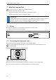
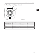
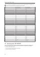
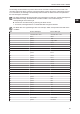
Table Of Contents
- Contents
- 1 Preliminary note
- 2 Safety instructions
- 3 Intended use
- 4 Items supplied
- 5 Function
- 5.1 Device overview
- 5.2 IO-Link
- 5.2.1 General information
- 5.2.2 Device-specific information
- 5.2.3 Device-specific parameters
- 5.2.3.1 Parameter “Data Hold Time”
- 5.2.3.2 Parameter "Auto-Read/Write Address"
- 5.2.3.3 Parameter "Auto-Read/WriteData Length"
- 5.2.3.4 Parameter "ID Tag Memory Area for Auto-Read/Write"
- 5.2.3.5 Parameter “ID Tag Access Password"
- 5.2.3.6 Parameter "ID Tag Selection Target
- 5.2.3.7 Parameter "ID Tag Selection Mask”
- 5.2.3.8 Parameter "ID Tag Selection Start Bit”
- 5.2.3.9 Parameter "ID Tag Selection Length”
- 5.2.3.10 Parameter "RSSI Filter Lowest Value”
- 5.2.3.11 Parameter "RSSI Filter Highest Value”
- 5.2.3.12 Parameter "Activate RSSI Filter”
- 5.2.3.13 Parameter “Antenna Output Power for Read Access"
- 5.2.3.14 Parameter “Antenna Output Power for Write Access"
- 5.2.3.15 Parameter "ID Tag Detection Mode”
- 5.3 ID tag
- 6 Mounting
- 7 Electrical connection
- 8 Operating and display elements
- 9 Operation
- 9.1 Status bits
- 9.2 Operating mode "SINGLE EPC
- 9.3 Operating Mode “READ DATA AUTO"
- 9.4 Operating Mode “WRITE DATA AUTO"
- 9.5 Operating mode "EPC REPORT
- 9.6 Operating mode "EPC LIST
- 9.7 Operating mode "WRITE EPC”
- 9.8 Operating mode "READ DATA
- 9.9 Operating mode "WRITE DATA”
- 9.10 Operating mode "LOCK DATA”
- 9.11 Error values when executing commands
- 10 Maintenance, repair and disposal
- 11 Approvals / standards
- Glossary

DTI801 DTI901 DTI911 DTI961
22
7 Electrical connection
The device must be connected by a qualified electrician.
Device of protection class III (PC III).
The electrical supply must only be made via PELV/SELV circuits.
u Disconnect power before connecting the device.
ATTENTION
The IP rating indicated in the data sheet is only guaranteed if the M12 connectors are firmly
screwed. The device can be damaged by insufficiently tightened M12 connectors.
u Screw the M12 connector to the device applying 1 to 1.5 Nm.
7.1 Wiring
u Connect the device to an IO-Link master using a M12 connection cable.
w Voltage is supplied via the IO-Link master.
Pin assignment Wiring
4
1
3
L
+
1
3
4
L
IO-Link
7.2 Connecting the functional earth
u Connect the device to an earth potential free from external voltage.
To ensure interference-free operation, connect the device to an earth potential free from
external voltage.
Connect the mounting plate to functional earth.
Fig.3: Mounting plate with mounted device
When the device is mounted on a mounting plate:
u Connect one of the 4 mounting bolts on the back of the device to the mounting plate.
u Connect the mounting plate to an earth potential free from external voltage.