
Operating Instructions

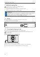
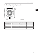
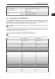
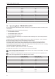
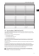
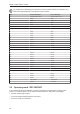
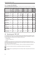
Table Of Contents
- Contents
- 1 Preliminary note
- 2 Safety instructions
- 3 Intended use
- 4 Items supplied
- 5 Function
- 5.1 Device overview
- 5.2 IO-Link
- 5.2.1 General information
- 5.2.2 Device-specific information
- 5.2.3 Device-specific parameters
- 5.2.3.1 Parameter “Data Hold Time”
- 5.2.3.2 Parameter "Auto-Read/Write Address"
- 5.2.3.3 Parameter "Auto-Read/WriteData Length"
- 5.2.3.4 Parameter "ID Tag Memory Area for Auto-Read/Write"
- 5.2.3.5 Parameter “ID Tag Access Password"
- 5.2.3.6 Parameter "ID Tag Selection Target
- 5.2.3.7 Parameter "ID Tag Selection Mask”
- 5.2.3.8 Parameter "ID Tag Selection Start Bit”
- 5.2.3.9 Parameter "ID Tag Selection Length”
- 5.2.3.10 Parameter "RSSI Filter Lowest Value”
- 5.2.3.11 Parameter "RSSI Filter Highest Value”
- 5.2.3.12 Parameter "Activate RSSI Filter”
- 5.2.3.13 Parameter “Antenna Output Power for Read Access"
- 5.2.3.14 Parameter “Antenna Output Power for Write Access"
- 5.2.3.15 Parameter "ID Tag Detection Mode”
- 5.3 ID tag
- 6 Mounting
- 7 Electrical connection
- 8 Operating and display elements
- 9 Operation
- 9.1 Status bits
- 9.2 Operating mode "SINGLE EPC
- 9.3 Operating Mode “READ DATA AUTO"
- 9.4 Operating Mode “WRITE DATA AUTO"
- 9.5 Operating mode "EPC REPORT
- 9.6 Operating mode "EPC LIST
- 9.7 Operating mode "WRITE EPC”
- 9.8 Operating mode "READ DATA
- 9.9 Operating mode "WRITE DATA”
- 9.10 Operating mode "LOCK DATA”
- 9.11 Error values when executing commands
- 10 Maintenance, repair and disposal
- 11 Approvals / standards
- Glossary

DTI801 DTI901 DTI911 DTI961
24
9 Operation
The device supports different operating modes. An operating mode is set with the command value in
the process data output image.
Command value Operating mode Description
0x00 SINGLE EPC Read and provide an EPC
0x01 READ DATA AUTO Auto-read data
0x02 WRITE DATA AUTO Auto-write data
0x03 EPC REPORT Create an EPC report
0x04 EPC LIST Create an EPC list
0x05 WRITE EPC Write EPC
0x06 READ DATA Read data
0x07 WRITE DATA Write data
0x08 LOCK DATA Lock data
All operating modes use the same status bits and error values in the process images.
In addition to the operating modes the internal antenna of the device can be deactivated. If the
antenna is deactivated, the device can still be addressed via IO-Link, but the device no longer
generates a high-frequency signal. ID tags are not detected by the device. By deactivating the
antenna, interference between devices installed next to each other can be avoided.
The device is activated and deactivated via the bit“ Antenna deactivate“ in the process data output
image. The status of the antenna is read via the bit "Antenna deactivated" in the process data input
image.
9.1 Status bits
Process input
Bit 7 6 5 4 3 2 1 0
Name Tag Over-
flow
Buffer over-
flow
Antenna de-
activated
Tag present Cmd End Cmd Start
Acknowl-
edge
Process output
Bit 7 6 5 4 3 2 1 0
Name Cmd Anten-
na deacti-
vate
Cmd Start
Status bit Value Description
Tag Overflow 0 ID tag processing OK
1 More ID tags are detected than can be processed
Buffer overflow 0 Data transmission OK
1 Data cannot be transmitted fast enough via IO-Link (only in operating
mode "EPC REPORT")
Antenna deactivated 0 Antenna activated, device ready to receive
1 Antenna deactivated, device not ready to receive
Tag present 0 No ID tag in the range of the device
1 ID tag detected
Cmd End 0 Read/write operation not started or active
1 Read/write operation terminated
Cmd Start Acknowledge 0 Start of a read/write operation not acknowledged