
Operating Instructions

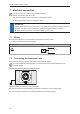
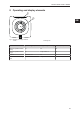
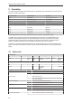
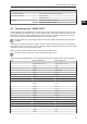
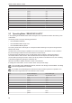
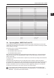
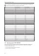
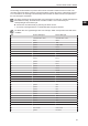
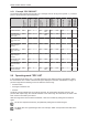
Table Of Contents
- Contents
- 1 Preliminary note
- 2 Safety instructions
- 3 Intended use
- 4 Items supplied
- 5 Function
- 5.1 Device overview
- 5.2 IO-Link
- 5.2.1 General information
- 5.2.2 Device-specific information
- 5.2.3 Device-specific parameters
- 5.2.3.1 Parameter “Data Hold Time”
- 5.2.3.2 Parameter "Auto-Read/Write Address"
- 5.2.3.3 Parameter "Auto-Read/WriteData Length"
- 5.2.3.4 Parameter "ID Tag Memory Area for Auto-Read/Write"
- 5.2.3.5 Parameter “ID Tag Access Password"
- 5.2.3.6 Parameter "ID Tag Selection Target
- 5.2.3.7 Parameter "ID Tag Selection Mask”
- 5.2.3.8 Parameter "ID Tag Selection Start Bit”
- 5.2.3.9 Parameter "ID Tag Selection Length”
- 5.2.3.10 Parameter "RSSI Filter Lowest Value”
- 5.2.3.11 Parameter "RSSI Filter Highest Value”
- 5.2.3.12 Parameter "Activate RSSI Filter”
- 5.2.3.13 Parameter “Antenna Output Power for Read Access"
- 5.2.3.14 Parameter “Antenna Output Power for Write Access"
- 5.2.3.15 Parameter "ID Tag Detection Mode”
- 5.3 ID tag
- 6 Mounting
- 7 Electrical connection
- 8 Operating and display elements
- 9 Operation
- 9.1 Status bits
- 9.2 Operating mode "SINGLE EPC
- 9.3 Operating Mode “READ DATA AUTO"
- 9.4 Operating Mode “WRITE DATA AUTO"
- 9.5 Operating mode "EPC REPORT
- 9.6 Operating mode "EPC LIST
- 9.7 Operating mode "WRITE EPC”
- 9.8 Operating mode "READ DATA
- 9.9 Operating mode "WRITE DATA”
- 9.10 Operating mode "LOCK DATA”
- 9.11 Error values when executing commands
- 10 Maintenance, repair and disposal
- 11 Approvals / standards
- Glossary

DTI801 DTI901 DTI911 DTI961
26
Byte Process data output Process data input
22 ignored 0x00
23 ignored 0x00
24 ignored 0x00
25 ignored 0x00
26 ignored 0x00
27 ignored 0x00
28 ignored 0x00
29 ignored 0x00
30 ignored block counter
31 ignored error value
9.3 Operating Mode “READ DATA AUTO"
In the operating mode "READ DATA AUTO" the bytes 0 to 27 represent the data in the memory area
of the device.
The memory area is set by the following parameters:
• "Auto-Read/Write Address",
• "Auto-Read/Write Data Length” and
• "Auto-Read/Write Memory Bank".
For memory areas with a data length of < 28 bytes the data remaining in the process image is filled
with the value 0x00.
The data in the process image is updated as soon as an ID tag is in the detection zone. The data in
the process image is valid as soon as the status bit "Cmd End" is set.
If the ID tag leaves the detection zone, the data bytes remain constant in the process image in
accordance with the data hold time. After the data hold time has elapsed, the data bytes in the
process data input image are reset to 0x00. If the ID tag remains in the detection zone, the re-reading
of the data is triggered by setting the "Cmd Start" bit.
Whenever the data is updated, the block counter is incremented.
If reading was unsuccessful, an error value is shown in the process image.
In the operating mode "READ DATA AUTO", the EPC of an ID tag is not transmitted. The ID tag
must be assigned based on the data.
The smaller the set data length, the less time the device needs to perform an operation. As a
result, the ID tag's dwell time in the detection zone is shorter.
Byte Process data output Process data input
0 command value = 0x01 command value = 0x01
1 status status
2 ignored data 0
3 ignored data 1
4 ignored data 2
5 ignored data 3
6 ignored data 4
7 ignored data 5
8 ignored data 6
9 ignored data 7