USB pedalboard controller/audio interface for iOS, Mac, PC.
Contents Table of Contents Contents 2 English 3 Power adapter information 3 iRig Stomp I/O 3 Register your iRig Stomp I/O 4 1 Installation and setup 4 1.1 iOS Devices 4 1.2 MAC/PC 8 2 Operating modes 9 3 Live Mode 10 3.1 Using iRig Stomp I/O with AmpliTube 10 3.2 Preset mode 10 3.3 Stomp mode 12 3.4 Expression pedal 13 3.5 Looper 13 3.6 Tuner 14 3.7 Tap tempo 15 3.8 MIDI IN/OUT ports 15 4 Audio/MIDI interface and foot controller 15 4.1 Using iRig Stomp I/O as a generic MIDI controller 15 4.
English Power adapter information Use only the specified AC adaptor you can buy at: www.ikmultimedia.com/irigpsu3a Use only the specified AC adaptor (iRig PSU 3A) and make sure the line voltage at the installation matches the input voltage specified on the AC adaptor’s body. IK Multimedia will not be responsible of any damage caused by usage of any AC adaptor other than the specified one (iRig PSU 3A).
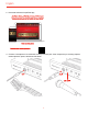
English Register your iRig Stomp I/O By registering, you can access technical support, activate your warranty and receive free JamPoints™ which will be added to your account. JamPoints™ allow you to obtain discounts on future IK purchases! Registering also keeps you informed of all the latest software updates and IK products. Register at: www.ikmultimedia.com/registration 1 Installation and setup iRig Stomp I/O can be USB bus powered or powered with the external PSU (included).
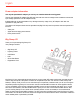
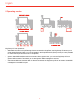
English 2. Download and launch AmpliTube App; 3. Connect a microphone or an instrument to the input combo jack. If the microphone you are using requires external phantom power, activate the 48V switch.
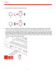
English 4. Adjust the input level with the gain potentiometer. 5. Connect a mixer, an amplifier or a PA system to the stereo line outputs. It is possible to control the output volume with the Volume potentiometer on the top panel. These are floating balanced output. This kind of output approximately simulates a floating transformer winding; if both hot and cold outputs are driving signal lines, then the outputs are balanced, as if a centre- tapped output transformer were being used.
English 6. Connect your headphones to the headphone output. It is possible to control the output volume with the Volume potentiometer on the top panel. 7. If needed, connect up to two footswitch/expression pedals to the TRS connector on iRig Stomp I/O. 8. If needed, you can connect external MIDI devices to the physical MIDI ports (Input/Output).
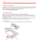
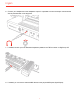
English 1.2 MAC/PC 1. Connect the USB cable to the iRig Stomp I/O port and to a free USB port on your MAC/PC (the required power is supplied by the USB host). 2. Download and launch the AmpliTube App. 3. Connect a microphone or an instrument to the input combo jack. If the microphone you are using requires external phantom power, activate the 48V switch. Adjust the input level with the gain potentiometer. 4. Connect a mixer, an amplifier or a PA system to the stereo line outputs.
English 2 Operating modes iRig Stomp I/O can operate as: • dedicated controller for AmpliTube app. When connected to AmpliTube, the iRig Stomp I/O allows you to recall presets (Default mode) or turn on/off pedals in the AmpliTube chain (Stomp mode). It is also possible to control the Looper and the Tuner on AmpliTube; • generic Audio/MIDI interface and foot controller. With a generic host, you can use iRig Stomp I/O as a generic MIDI controller.
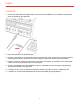
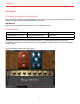
English 3 Live Mode 3.1 Using iRig Stomp I/O with AmpliTube When connected to a device running AmpliTube you can access to a full set of controls. Below we describe the operational mode when the app/software AmpliTube is running. USB MIDI port Make sure to have selected “iRig Stomp IO Control” as MIDI IN/OUT port. 3.2 Preset mode Switch combination Function MIDI message sent Pressing Switch 3+4 >1sec.
English The LIVE section will appear in the preset (default) mode: In this mode, the 4 footswitches send Program Change (PC) messages in bank of four (e.g.: from 0 to 3). By pressing and holding the footswitch 2 for more than 1 second the bank increase of 1. Now the 4 footswitches send PC messages increased of one bank (e.g: from 4 to 7). By pressing and holding the footswitch 1 for more than 1 second the bank decrease of 1. Now the 4 footswitches send PC messages decreased of one bank (e.g.
English 3.3 Stomp mode Switch combination Function MIDI message sent Pressing Switch 3+4 >1sec. Stomp Mode/Preset Mode CC#39 val 127 MIDI CH 1 The iRig Stomp I/O has two main modes: Preset and Stomp. To switch between the two, simply press simultaneously footswitches 3 and 4 for more than 1 second. When in Stomp mode, the LED on the top panel will light up red. Launch AmpliTube and tap on the LIVE section.
English The 5 footswitch’s LEDs show you the current status of the stomp’s slot in AmpliTube: Empty slot Stomp off Stomp on LED off LED green LED red The footswitches 1 to 5 correspond to the first four slots in AmpliTube, plus the pedal slot. If the slot in AmpliTube is empty, corresponding LED is Off; if the slot have a stomp in it, but it is off, then the corresponding LED in On green; if the slot have a stomp in it, and it is on, then the corresponding LED in On red. 3.
English When iRig Stomp I/O is in looper mode, the 4 footswitches act as: Footswitch SW 1 SW 2 SW 3 Function Selects previous track Selects next track Start-Stop recording/stop playback of the selected track SW 4 (Holding for >1sec.) Delete selected track MIDI CH 1 Message sent CC#28 and CC#58 when holding for >1 sec. CC#29 and CC#59 when holding for >1 sec. CC#30 and CC#60 when holding for >1 sec. CC#31 and CC#61 when holding for >1 sec.
English When iRig Stomp I/O is in tuner mode the footswitche’s LEDs show the tuning status. Tuning Note tuned Note low in tune Note very low in tune Note up in tune Note very up in tune LED status LEDs 2 and 3 turned on (green) LED 2 turned on (red) LED 1 and 2 turned on (red) LED 3 turned on (red) LED 3 and 4 turned on (red) 3.7 Tap tempo Switch combination Function MIDI message sent Holding Switch 4 >1sec.
English 4.2 Default mode Switch combination Function MIDI message sent Pressing Switch 3+4 >1sec. Stomp Mode/Default Mode CC#39 val 0 MIDI CH 1 The iRig Stomp I/O has two main modes: Default and Stomp. To switch between the two, simply press simultaneously footswitches 3 and 4 for more than 1 second. When in Stomp mode, the LED on the top panel will light up red. When in default mode, as generic controller, the 4 footswitches send Program Change (PC) messages in bank of four (e.g.: from 0 to 3).
English Switch 1 When released send When hold for >1 sec send Switch 2 CC#20 CC#21 CC#22 - toggle toggle mode toggle mode mode CC#23 toggle mode Virtual Pedal Switch CC#26 – CC#11 toggle mode CC#91 Tap tempo --- CC#90 Switch 3 Switch 4 Disabled --- MIDI CH 1 The 4 footswitch’s LEDs turn on Red when a CC value 127 is sent from the Stomp I/O and turn off when a CC value 0 is sent from the Stomp I/O. 4.
English 5 Stand alone MIDI foot controller 5.1 Using iRig Stomp I/O as stand alone controller (no computer required) With no device connected, the iRig Stomp I/O can be used to send MIDI messages thru the MIDI OUT port. Messages sent are the same of generic MIDI controller, but all the MIDI messages are routed to the MIDI OUT port.
English 9 Bootloader To access to the bootloader (only needed for firmware update), keep pressed the footswitch 4 while power up iRig Stomp I/O. 10 Specifications Common Conversion: 24-bit A/D, 24-bit D/A Sampling Rate: 44.1 kHz, 48 kHz, 88.2 kHz and 96 kHz Power: USB bus powered (when used with a computer) or DC IN Device Connection: USB B-Type and Mini-DIN Enclosure: metal sheet Microphone Input Connector: balanced female 3-pin XLR.
English Maximum Output Level: +13 dBu into 600 Ohms balanced load Frequency Response: from 10 Hz to 21 kHz (+/- 0.2dB) Output Dynamic Range: 102 dB(A) Output Impedance: 150 Ohms balanced Floating Balanced Outputs MIDI Input/Output Connector: 2x 5-pin DIN Warranty Please visit: www.ikmultimedia.com/warranty for the complete warranty policy. Support and more info www.ikmultimedia.com/support www.irigstompio.
Regulatory FCC statement This device complies with Part 15.107 and 15.109 Class B of the FCC Rules CFR47: October 2010. Operation is subject to the following two conditions: 1. This device may not cause harmful interference. 2. This device must accept any interference received, including interference that may cause undesired operation. Changes or modifications not expressly approved by the party responsible for compliance could void the user’s authority to operate the equipment.