
User's Manual


Document name: ICC-A-1 connectivity module description Revision: 0.1
Document ID: SCDOC-129-680 Revision date: 2017-04-24
FCC ID: FHO-ICC-A-1
IC ID: 10912A-ICCA1
© Inter IKEA Systems B.V. 2016 Page 13 of 19
Figure 9 - Mounted 90 degree angle
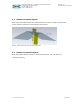
Figure 10 - Flat board-to-board connection
2.4.1 Noisy signals
Keep potentially noisy traces and components of the motherboard as far as possible from
the antenna to prevent dispense of the module.
3 Power supply for ICC-A-1
3.1 Regulated power supply
ICC-A-1 can be supplied from a regulated power supply down to 2.1 V in all conditions.
During peak load transients, power supply can be up to 100mA when using high power
mode. The product designer shall verify unconditional stability during peak load to
secure that voltage is not dropping below 2.1V.
The actual design of the regulator affects the decoupling capacity. Make sure that no
noise is injected via the power supply that can impact the analogue parts of the radio.
3.2 Coin cell battery operation
ICC-A-1 can be operated from a single 3.0V coin cell battery. A minimum of sustaining
2.1V during all peak transients until battery end of life is required to guarantee proper
operation.
Make sure to fulfil the below requirements:
• Add enough decoupling to the device to avoid brown out during transient load in
TX burst. 20uF < 200uF.
Soldered