
User's Manual


Document name: ICC-A-1 connectivity module description Revision: 0.1
Document ID: SCDOC-129-680 Revision date: 2017-04-24
FCC ID: FHO-ICC-A-1
IC ID: 10912A-ICCA1
© Inter IKEA Systems B.V. 2016 Page 6 of 19
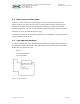
1.2 Pin description
The pin out is flexible and all pins can be configured as analogue port or data channel,
such as I2C. Each GPIO has its own mux configuration and set of PU and PD. The
software is defied for each product.
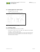
The pin number is counted from the lower left corner, see Figure 2.
Figure 2 - Overview pin out numbering for ICC-A-1
Pin description
Pin
number
Logic
number
Notes Pin
number
Logic
number
Notes
1 GND Connected to main
ground
10 RESETn Hardware reset
2 PB15 GPIO 11 VDD Power supply
3 PB14 GPIO 12 GND Ground
4 PC10 GPIO 13 PB13 GPIO
5 PC11 GPIO 14 PB12 GPIO
6 PF0 DBG_SWCLKTCK 15 PA1 GPIO
7 PF1 DBG_SWDIOTMS 16 PA0 GPIO
8 PF2 DBG_SWO 17 PC11 FTM
9 GND GND
11
12
13
14
15
16
1
2
3
4
5
6
7
8
9
10