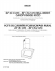
24" (61.0 cm) - 30" (76.2 cm) WALL-MOUNT CANOPY RANGE HOOD For questions about parts, accessories features, operation/performance, or service, call: 1-866-664-2449. HOTTEDE CUISINII:RE POUR MONTAGE MURAL 24" (61 cm) - 30" (76,2 cm) Au Canada, pour assistance, Table of Contents/Table installation ou service, composez des matieres ............................................................................. IMPORTANT: READ AND SAVE THESE INSTRUCTIONS. FOR RESIDENTIAL USE ONLY.
TABLEOF CONTENTS TABLEDESMATIERES RANGE HOOD SAFETY ................................................................. 3 INSTALLATION REQUIREMENTS ................................................ 5 Tools and Parts ............................................................................ 5 Location Requirements ................................................................ 5 Venting Requirements .................................................................. 6 Electrical Requirements ...............
RANGE HOOD SAFETY Your safety and the safety of others are very important. We have provided many important safety messages in this manual and on your appliance. Always read and obey all safety messages. This is the safety alert symbol. This symbol alerts you to potential hazards that can kill or hurt you and others. All safety messages will follow the safety alert symbol and either the word "DANGER" or "WARNING.
iMPORTANT SAFETY iNSTRUCTiONS WARNING: TO REDUCE THE RISK OF FIRE, ELECTRIC SHOCK, OR INJURY TO PERSONS, OBSERVE THE FOLLOWING: [] Use this unit only in the manner intended by the manufacturer. If you have questions, contact the manufacturer. [] Before servicing or cleaning the unit, switch power off at service panel and lock the service disconnecting means to prevent power from being switched on accidentally.
INSTALLATIONREQUIREMENTS • 2-6x70mmscrews _9_,_;;:_,C_ (} _[_ • 2 - 10 mm wall plugs Gather the required tools and parts before starting installation. Read and follow the instructions provided with any tools listed here. • 4 washers • 2 screwdriver bits for TORX®t screws Tools needed • Level • Drill with 11¼"(3.0 cm), 3/8"(9.5 mm), 7/64"(2.75 mm) and V8" (3.
10.7" 11.2" (27.3 cm) (28.4 cm) vc _ S t_equ/H_;mels%5 • Vent system must terminate to the outdoors, except for nonvented (recirculating) installations. • Do not terminate the vent system in an attic or other enclosed area. 31.9" (81 cm) rain • Do not use 4" (10.2 cm) laundry-type wall cap. 35.4" (90 cm) rain (non-vented recirculating installation) • Use metal vent only. Rigid metal vent is recommended. Plastic or metal foil vent is not recommended.
Roof Venting Wall Venting Non-vented (recirculating) E cQ sts Observe all governing codes and ordinances. .4 Ensure that the electrical installation is adequate and in conformance with National Electrical Code, ANSI/NFPA 70 (latest edition), or CSA Standards C22.1-94, Canadian Electrical Code, Part 1 and C22.2 No. 0-M91 (latest edition) and all local codes and ordinances.
INSTALLATIONINSTRUCTIONS It is recommended hood is installed. that the vent system be installed before 8. Mark centers of the 6 fastener locations through the template to the wall. IMPORTANT: All screws must be installed into wood. • Before making cutouts, make sure there is proper clearance within the ceiling or wall for exhaust vent. • Check your ceiling height and the hood height maximum before you select your hood. 9. 1. Disconnect 2.
3. Mark the mounting hole locations. i A 1. Using 2 or more people, hang range hood on 2 mounting hooks through the rectangular cutouts on back of hood. I ID J A. Vent cover bracket A B. Mounting hole locations C. Centerline on wall 4. Drill 3/8"(9.5 mm) holes for wall anchors and insert anchors flush with the wall. 5. Install vent cover bracket to wall about 1/8"(3 mm) away from the ceiling with drywall anchors and the 6 x 70 mm screws supplied. i I _i!i _.......................... A B i .
4= Non-Vented 1. (recirculating) Installation Run 3 wires, black, white and green (14AWG), in 1/2"conduit from service panel to terminal box. Use caulking to seal opening. Connect the deflector to the vent cover bracket using the four 3.5 x 9.5 mm screws 3rovided. A B i / B C D F A. Vent cover bracket A. UL listed or CSA approved strain relief B. Home power supply cable C. Terminal box D. Black wires B. 3.5 x 9.5 mm screws 2.
4. C,,omD/ete _,1_ 1= i ,1,_1 , ,_ , ,_ I/ I*+>/;i l@JlllI@J411 sy/_, Pull filter toward the front and insert into front channel. / Install vent cover. Push lower cover down onto hood and lift upper cover to ceiling and install with two 2.9 x 9.5 mm screws. Connect the upper and lower vent covers with two 3.5 x 9.5 mm screws apiece from the inside of the hood. E Install the Front Panel 5. Align the pins on the range hood with the lock springs on the front panel. 6.
RANGE HOOD USE The range hood is designed to remove smoke, cooking vapors and odors from the cooktop area. For best results, start the hood before cooking and allow it to operate several minutes after the cooking is complete to clear all smoke and odors from the kitchen. RANGE HOOD CARE IMPORTANT: Clean the hood and grease filter frequently according to the following instructions. Replace grease filter before operating hood. Be sure lights are cool before cleaning the hood.
To Replace Charcoal Filters 1. Turn blower and lights off. Check that halogen lamp is cool. CharcoalFilter- ForNon-Vented (recirculating) Installations The charcoal filter is not washable nor reusable. They should be changed every 4 months in normal use. The charcoal filter captures unpleasant cooking odors. To Install Charcoal Filters 2. Remove the front panel by extracting them outward. 3. 4. Remove the metal grease filter by pushing handle toward the rear and pull downward.
WIRING DIAGRAM LIGHT K5 ON K6 OFF OFF ON LINE MAIN BOARD _O -- @ BRW ---_€ i GRY BLK BLU COLOR TABLE --" BRW 14 CI - WHT _fe RED (,, --_e-Ce.
ASSISTANCEOR SERVICE Before calling for assistance or service, please check "Troubleshooting." It may save you the cost of a service call. If you still need help, follow the instructions below. When calling, please know the purchase date and the complete model and serial number of your appliance. This information will help us to better respond to your request. If you need replacement parts If you need to order replacement parts, we recommend that you use only factory specified parts.
IKEAMAJOR APPLIANCE WARRANTY How long is the IKEA limited warranty valid? This limited warranty is valid for five years from the date of purchase, when this major appliance is operated and maintained according to instructions attached to or furnished with the product, unless the appliance is named LAGAN in which case this limited warranty is valid for one year from the date of purchase.
Keep this book and your sales slip together for future reference. You must provide proof of purchase or installation date for in-warranty service. Write down the following information about your major appliance to better help you obtain assistance or service if you ever need it. You will need to know your complete model number and serial number. You can find this information on the model and serial number label located on the product.
IMPORTANTES iNSTRUCTiONS DE SECURITE AVERTISSEMENT : POUR REDUIRE LE RISQUE D'INCENDIE, CHOC ¢:LECTRIQUE OU DOMMAGES CORPORELS, RESPECTER LES INSTRUCTIONS SUIVANTES : m Utiliser cet appareil uniquement dans les applications envisag_es par le fabricant. Pour toute question, contacter le fabricant.
EXlGENCESD'INSTALLATION Pi_ces fournies Rassembler les outils et pieces necessaires avant de commencer I'installation. Lire et suivre les instructions fournies avec les outils indiques ici. Retirer les pieces des emballages. Verifier que toutes les pieces sont presentes.
Installation dans une r_sidence mobile L'installation de cette hotte doit satisfaire aux exigences de la norme Manufactured Home Construction Safety Standards, Titre 24 CFR, partie 328 (anciennement Federal Standard for Mobile Home Construction and Safety, Titre 24, HUD, partie 280); Iorsque cette norme n'est pas applicable, I'installation doit satisfaire aux criteres de la plus recente edition de la norme Manufactured Home Installation 1982 (Manufactured Home Sites, Communities and Setups)ANSI A225.
Installations pour r6gions & climat froid On devrait installer un clapet antireflux additionnel pour minimiser le reflux d'air froid, et incorporer un 61ement non metallique d'isolation thermique pour minimiser la conduction de chaleur par I'intermediaire du conduit d'evacuation, de I'interieur de la maison & I'exterieur. Le clapet anti-reflux doit 6tre place du c6te air froid par rapport & I'el6ment d'isolation thermique.
Observer les dispositions vigueur. de tousles codes et reglements en Si le domicile est equipe d'un c&blage en aluminium, suivre les instructions suivantes • L'installation electrique dolt satisfaire les exigences de la plus recente edition de la norme National Electrical Code, ANSl/NFPA 70, ou de la norme CSA C22.1-94, Code canadien de I'electricite, partie 1 et C22.2 No 0-M91 (derniere edition) et de tousles codes et reglements en vigueur. 1. 2.
9. Percer des avant-trous de %4" (2,75 mm) sur tousles emplacements pour la pose des vis dans du bois. 10. Fixer 2 crochets de montage au mur aux emplacements marqu6s sur le gabarit. A ...... Derni_res 1. B 2. I 3. A. Crochets de montage B. Axe central sur lemur Bride de cache-conduit - Assemblage et installation 1. Assembler les trois composants de la bride de cache-conduit - utiliser les quatre vis 4 x 8 mm fournies.
Pour installations uniquement 1. Connecter avec d_charge le circuit d'evacuation A _ I'ext_rieur 3. Installer le conduit d'air entre le raccord de transition et le deflecteur. 4. Utiliser des brides de serrage pour sceller chaque connexion. 5. Enlever le filtre a graisse. sur le raccord de transition. ...... A. Circuit d'_vacuation B. Raccord de transition 2. Utiliser des brides pour assurer I'etanch6it6 des jointures. Installation sans d_charge _ I'ext_rieur (recyclage) 1.
4, Acheminer 3 conducteurs de calibre 14 (noir, blanc et vert) dans un conduit de 1/2"entre le tableau de distribution et la boite de connexion. Utiliser un calfeutrant pour assurer I'etanch6it6 au niveau de chaque ouverture. ............................. B Ach 1, @on Installer le cache-conduit. Pousser la section inferieure du cache-conduit vers le bas sur la hotte et soulever la section superieure du cache-conduit vers le plafond et installer les 2 vis de 2,9 x 9,5 mm.
..... Pour les installations sans decharge a I'exterieur (recyclage), installer le filtre a charbon sur la grille du carter du ventilateur; aligner les broches (B) du carenage avec les ouvertures (0), et faire pivoter le filtre dans le sens horaire pour le verrouillage. R6peter pour I'autre filtre a charbon. 1. A A C A. Carter du ventilateur B. Broches C. Ouvertures Pour tousles types d'installations, inserer le bord arriere ou le filtre metallique dans la rainure arriere de I'ouverture du filtre. 3.
ENTRETIEN DE LA HOTTE IMPORTANT : Nettoyer la hotte et les filtres & graisse regulierement en suivant les instructions suivantes. Remettre en place les filtres & graisse avant de mettre en marche la hotte. Avant d'entreprendre le nettoyage de la hotte, attendre le refroidissement des lampes. Surfaces externes Nettoyer la hotte avec un detergent doux et un chiffon doux. Pour eviter d'endommager la surface externe, ne pas utiliser un produit de nettoyage abrasif ou un tampon de laine d'acier.
Remplacement des filtres _ charbon 1. Commander I'arr_t du ventilateur et I'extinction Verifier que la lampe & halogene est froide. Remplacement des lampes. d'une lampe _ halog_ne Interrompre I'alimentation de la hotte; attendre le refroidissement de la lampe & halogene. Pour eviter d'endommager ou de reduire la Iongevit6 de I'ampoule neuve, ne pas toucher I'ampoule avec les doigts nus. Remplacer I'ampoule en la tenant avec un mouchoir papier ou des gants de coton. 2.
SCHI_MA DE CABLAGE N-LL SE 1TTA JA JA TRANSFOR- MATEUR ISEC_R _ I NIVEAU MAX MOYEN LUMIERE K5 MARCHE K6 ARRET ARRET MARCHE BL N BU JA PHASE JA BL R N f JA-VE TABLEAU DE CORRESPONDANCE MAR -(o JA --" MAR ,_ IIJ DES COULEURS N NOIR R BU BLEU BL ROUGE BLANC MAR MARRON JA JAUNE VE VERT JA-VE JAUNEiVERT GRIS GRIS BL R R MOTEUR GRIS VITESSE N BU N (,- BU 1 2 3 4 K1 MARCHE ARRET ARRET ARRET K2 ARRET MARCHE ARRET ARRET K3 ARRET ARRET MARCHE ARRET K4 ARRET ARRET
ASSISTANCEOU SERVICE Avant de faire un appel pour assistance ou service, consulter la section "Depannage". Ce guide peut vous faire economiser le coQt d'une visite de service. Si vous avez encore besoin d'aide, suivre les instructions ci-dessous. Lors d'un appel, veuillez connaYtre la date d'achat, le numero de modele et le numero de serie au complet de I'appareil. Ces renseignements nous aideront & mieux repondre a votre demande.
GARANTIEDESGROS APPAREILSMENAGERSIKEA Pendant combien de temps la garantie limitde IKEA est-elle valide? Cette garantie limitee est valide pendant cinq ans a compter de la date d'achat Iorsque ce gros appareil menager a et6 utilise et entretenu conformement aux instructions jointes au produit ou fournies avec celui-ci, sauf si I'appareil porte le nom LAGAN, auquel cas cette garantie limitee est valide pendant un an & compter de la date d'achat.
Conservez ce manuel et votre re_u de vente ensemble pour r_f_rence ult_rieure. Pour le service sous garantie, vous devez presenter un document prouvant la date d'achat ou d'installation. Inscrivez les renseignements suivants au sujet de votre gros appareil menager pour mieux vous aider a obtenir assistance ou service en cas de besoin. Vous devrez connaitre le numero de modele et le numero de serie au complet. Vous trouverez ces renseignements sur la plaque signaletique situ6e sur le produit.