INSTRUCTION MANUAL Color Camera MODEL ISD-A33S OUTDOOR USE WARNING WARNING – TO PREVENT FIRE OR ELECTRIC SHOCK, DO NOT EXPOSE THIS APPLIANCE TO RAIN OR MOISTURE. The apparatus shall not be exposed to dripping or splashing and that no objects filled with liquids, such as vases, shall be placed on the apparatus. ct s e co produ Ikegami Tsushinki Co., Ltd.
Thank you for choosing this Ikegami Hyper Wide Dynamic DPS Dome Camera. Please read this Instruction Manual carefully to keep your Ikegami camera at peak performance for longer service period. This unit is a dome-type 1 CMOS color camera incorporating a special auto-iris varifocal lens and making use of a 1/3.2” type digital pixel sensor system (DPS).
The exclamation point within an equilateral triangle is intended to alert the user to the presence of important operating and maintenance (servicing) instructions in the literature accompanying the appliance. NOTE: This equipment has been tested and found to comply with the limits for a Class A digital device, pursuant to part 15 of the FCC Rules. These limits are designed to provide reasonable protection against harmful interference when the equipment is operated in a commercial environment.
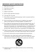
IMPORTANT SAFETY INSTRUCTIONS 1) Read these instructions. 2) Keep these instructions. 3) Heed all warnings. 4) Follow all instructions. 5) Do not use this apparatus near water. 6) Clean only with a dry cloth. 7) Do not block any of the ventilation openings. Install in accordance with the manufacturer's instructions. 8) Do not install near any heat sources such as radiators, heat registers, stoves, or other apparatus (including amplifiers) that produce heat.
14) Refer all servicing to qualified service personnel. Servicing is required when the apparatus has been damaged in any way, such as power supply cord or plug is damaged, liquid has been spilled or objects have fallen into the apparatus, the apparatus has been exposed to rain or moisture, does not operate normally, or has been dropped. 15) CAUTION - These servicing instructions are for use by qualified service personnel only.
1. Handling Precautions • Do not expose the internal mechanism of the camera in a watersplashed or highly humid environment. • Do not use the camera where the ambient temperature drops below -10°C or rises above +50°C. The images and component parts may be adversely affected or the camera may not function correctly.
3. Features (1) Compact Dome Configuration The camera lens is housed in a compact dome configuration to enable surveillance with images without having to be aware that a camera is installed. (2) Integrated unit with triaxial adjustment varifocal lens in a single unit This is an integrated type design featuring a varifocal lens. Because it can operate with triaxial adjustment, even when attached to a wall, it can be adjusted to an arbitrary imaging range.
4. Camera Installation 4-1. Pre-work before installation 68.5 For camera fixing, two holes are needed. Holes for camera fixing 4-2. Mounting the camera (Ceiling) Put two fixing screws leaving about 5mm clearance. Those two screws will be tightened later to secure the dome camera. Put the cable wiring through the center hole of the camera base ① , and align two key hole slot to the screws. And turn the unit clockwise until it stops and tighten two fixing screws. Put back the dome cover.
5.
① Lens fixing screws (elevation) These are screws to fix the camera in the desired elevation position. Fix these screws after setting the viewing position. ② Vari-focal lens Can be used with flexible angle of view using varifocal lens. ③ Switches for camera setup Refer to Section 8 (Operating Procedure) ④ Test monitor output Connect accessory MON.OUT output harness. ⑤ Power cable This is a power cable. Non-polarity AC24V (AC 21.6V ~ 26.4V) or DC12V has to be connected.
6. Connections Be sure not to apply power before making connections. 6-1. Power cable Use DC12V (10.5V to 15V), or AC24V (± 10%) in both 60Hz and 50Hz. * This installation should be made by a qualified service person and should conform to all local codes. 6-2. Video output cable (BNC) This is a video output terminal. To be use an ordinary video output, for monitors, or switcher. 6-3. Test monitor output (MON.OUT) • Image output terminal used when installing the camera.
7. Angle and Lens adjustment 7-1. Angle adjustment Before doing this, the clear dome cover has to be removed. ●●Remove the dome cover Turn the black section of the dome cover in a counterclockwise direction to remove. Pay attention not to drop a dome cover while doing this. Note: When imaging in a horizontal direction, the black section of the dome cover may be imaged so that part of the image is missing. Adjust the angle of vision in a horizontal direction so that the dome cover is not imaged.
8. Operating Procedure 8-1. User Setup This dome camera is provided with user setup function for picture quality, and camera ID. The setup menu is a tree type on-screen-display. When installing the camera it is possible to set up the various functions. 8-2. Names and functions of the setup bottons UP To select setup parameters DOWN (up and down) RIGHT To change setup parameters LEFT SET To get in or get out to setup mode, and to enter and execute procedures.
8-3-1. SETUP MENU 1/2 * The setting is not saved unless the menu is finished from EXIT. SETUP MENU DAY/NIGHT SHUTTER/AGC WDR/ATR BACKLIGHT WHITE BAL LENS AUTO ↵ AUTO ↵ WDR ↵ OFF ATW ↵ DC ↵ CAMERA RESET NEXT ↵ EXIT ↵ YES ↵ (1) DAY/NIGHT Selecting Day or Night is available. ① AUTO The image is automatically switched between high-quality color image for the day and highly-sensitive monochrome image for the night. Pressing the E button here opens the right-side window.
(2) SHUTTER/AGC It selects a shutter speed and a gain mode. ① AUTO It automatically adjust the sensitivity. AUTO SETUP Pressing the E button here opens HIGH LUMINANCE the right-side window. MODE SHUT+DC IRIS AE LEVEL 050 ・ MODE Setting whether the video level LOW LUMINANCE AGC ON adjustment is controlled by the DC iris or by the shutter is available. RETURN ↵ ・ AE LEVEL It adjusts the brightness of the entire video. It becomes brighter as the number becomes larger.
① HLC It is a function to increase the visibility of the surrounding area by using a mask when a light source exists in the video. ② BLC It is a blacklight correcting function. (5) WHITE BAL WHITE BAL Setting a white balance is available. ① ATW ENVIRONMENT INDOOR SPEED 150 It is a setting that automatically DELAY CNT 001 judge the condition of playing video and conducts adjustments. Pressing the E button here opens the rightside window.
・ MODE Selecting either one of automatic control, open, or close is available for diaphragm. ・ SPEED This is a setting available only when the MODE is automatic control. Changing the opening/closing speed of diaphragm is available. (7) CAMERA RESET It returns the setup contents to the default setting before shipping from the factory. (8) NEXT Switching to the next page is available. (9) EXIT Pressing the E button here opens the EXIT right-side window.
8-3-2. SETUP MENU 2/2 * The setting is not saved unless the menu is finished from EXIT. SETUP MENU PICT ADJUST DNR DEFOG CAMERA ID PRIVACY ↵ ↵ OFF OFF OFF BACK ↵ EXIT ↵ (1) PICT ADJUST Video inversion and adjustments of brightness, contrast, sharpness, hue, and intensity are available. Selecting PICT ADJUST and pressing the E button opens the rightside window. ① FLIP PICT ADJUST It flips the video vertically and horizontally.
(3) DEFOG It is used when the entire video looks foggy. The LEVEL consists of LOW, MID, HIGH. Select one according to the situation. (4) CAMERA ID The screen can display 26 characters x 2 lines. ① OFF CAMERA ID ② ON ABCDEFGHIJKLMNOPQRSTUV ● ID character setting WXYZ0123456789−! ♯$%&( )_ ,¥:;<=>?@\^*.x+/ Pressing the E button while CAMERA ID is ON opens the screen ←→↑↓ CLR POS ↵ on the right.
⑤ RIGHT It decides the right side position of the privacy mask area. ⑥ COLOR Changing the mask color is available. ⑦ TRANSP It decides the shades of the mask color. ⑧ MOSAIC It selects whether or not to apply mosaic process within the mask area.
9. Warranty and after-sale service A warranty accompanies this product. Read and fill out the warranty card that you have received at your dealer. Keep this card in a safe place. ●●Please consult Ikegami Electronics (U.S.A.) Inc. or Ikegami Electronics (Europe) GmbH or your dealer for full warranty information. Your dealer will repair or replace free of charge within the warranty period according to the warranty coverage.
10. Specifications (1) (2) (3) (4) (5) Image Sensor: 1/3.2-inch DPS CMOS sensor Pixel Number: Approx. 1,230,000 pixels,1280(H)×960(V) Scanning system: 525 TV lines / 59.94Hz, 2 : 1 interlace Sync system: Internal synchronization (Crystal-lock) Video output: VBS 1.0Vp-p/75 ohms MON.OUT 1.
(21) Dome cover: Inner and Outer, Double dome type (22) Size (Diameter & Height): ø124.2mm x 102.0mm (excluding protrusions) (23) Weight: Approx. 340g (24) Input/output connectors: • VIDEO OUT: BNC • Power input: open-ended wires • MONI.OUT Connector output (25) Supplied accessories: Instruction Manual: 1 Tapping screws to secure camera: 2 MONI.
Gracias por haber elegido esta cámara de domo DPS de gama dinámica hiperancha de Ikegami. Lea con mucha atención este Manual de instrucciones para mantener su cámara Ikegami en las mejores condiciones de funcionamiento durante muchos años. Esta unidad es una cámara en color de CMOS de tipo domo que incorpora un objetivo de variación focal de iris automático especial y que utiliza un sistema de sensor de píxeles digital de tipo de 1/3.2”.
El signo de exclamación dentro de un triángulo equilátero tiene la finalidad de avisar al usuario de la presencia de instrucciones de funcionamiento y mantenimiento (reparaciones) importantes en los manuales que acompañan al aparato. NOTA: Este equipo ha sido probado y ha demostrado cumplir con los límites establecidos para los dispositivos digitales de la clase A, en conformidad con el apartado 15 de los Reglamentos de la FCC.
INSTRUCCIONES IMPORTANTES DE SEGURIDAD 1) Lea estas instrucciones. 2) Conserve estas instrucciones. 3) Preste atención a todas las advertencias. 4) Siga todas las instrucciones. 5) No utilice este aparato cerca de agua. 6) Limpie solamente con un paño seco. 7) No bloquee ninguna de las aberturas de ventilación. Instale de acuerdo con las instrucciones del fabricante.
14) Solicite cualquier reparación a personal de servicio cualificado. La reparación se requerirá cuando el aparato se haya dañado de alguna forma, por ejemplo, cuando se haya dañado el cable o el enchufe de alimentación, se haya vertido líquido o hayan entrado objetos dentro del aparato, cuando el aparato haya estado expuesto a la lluvia o la humedad, cuando no funcione normalmente, o cuando haya caído.
1. Precauciones de manejo • No exponga el mecanismo interno de la cámara en un ambiente donde se salpique agua o exista mucha humedad. • No utilice la cámara donde la temperatura ambiental sea inferior a -10°C o superior a +50°C. Las imágenes y las piezas componentes podrían ser afectadas o la cámara podría funcionar mal.
3. Características (1) Configuración de domo compacta El objetivo de la cámara está alojado en una configuración de domo compacta para permitir la vigilancia con imágenes sin notar que hay una cámara instalada. (2) Unidad integrada con objetivo de variación focal de ajuste triaxial en una sola unidad Éste es un diseño de tipo integrado que se caracteriza por un objetivo de variación focal.
4. Instalación de la cámara 4-1. Trabajo anterior a la instalación 68.5 Para fijar una cámara se necesitan dos agujeros. Orificios para fijación de la cámara 4-2. Montaje de la cámara (Techo) Ponga dos tornillos de fijación dejando una separación de unos 5 mm. Estos dos tornillos se apretarán posteriormente para asegurar la cámara de domo. Pase el cableado a través del agujero central de la base de la cámara ① y alinee las dos ranuras tipo agujero para llave con los tornillos.
5.
① Tornillos de fijación del objetivo (elevación) Éstos son tornillos que bloquean la cámara en la posición de elevación deseada. Fije estos tornillos después de establecer la posición de visión. ② Objetivo de variación focal Puede utilizarse con ángulo de visión flexible utilizando el objetivo de variación focal. ③ Conmutadores para configuración de la cámara Consulte la sección 8 (Procedimiento de operación) ④ Salida de monitor de prueba Conecte el cable de salida de MON.OUT accesorio.
6. Conexión Asegúrese de no encender la cámara hasta después de finalizar todas las conexiones. 6-1. Cable de alimentación Utilice 12 V CC (10,5 V a 15 V) o 24 V CA (±10%) con frecuencia de 60 Hz y 50 Hz. * Esta instalación deberá hacerla un técnico de servicio cualificado, y deberá cumplir con todos los códigos locales. 6-2. Cable de salida de vídeo (BNC) Éste es un terminal de salida de vídeo. Se utiliza como salida de vídeo convencional para monitores o conmutador. 6-3.
7. Ajuste de ángulo y objetivo 7-1. Ajuste de ángulo Antes de hacer esto, la cubierta de domo tendrá que quitarse. ●●Extracción de la cubierta del domo Gire la sección negra de la cubierta de domo hacia la izquierda para extraerla. Tenga cuidado de no dejar caer la cubierta de domo al hacer este trabajo. Nota: Para captar imágenes en dirección horizontal, la sección negra de la cubierta de domo puede captarse y perderse parte de la imagen.
8. Procedimiento de operación 8-1. Configuración del usuario Esta cámara de domo está provista con una función de configuración del usuario para ajustar la calidad de la imagen, puesta de la identificación de la cámara. El menú de configuración es una visualización en pantalla en forma de árbol. Cuando instale la cámara podrá configurar varias funciones. 8-2.
8-3-1. SETUP MENU 1/2 *E l ajuste no se guardará a menos que se finalicee el menú desde EXIT. SETUP MENU DAY/NIGHT SHUTTER/AGC WDR/ATR BACKLIGHT WHITE BAL LENS AUTO ↵ AUTO ↵ WDR ↵ OFF ATW ↵ DC ↵ CAMERA RESET NEXT ↵ EXIT ↵ YES ↵ (1) DAY/NIGHT Se puede seleccionar Día o Noche. ① AUTO Las imágenes cambian automáticamente entre imágenes en color de alta calidad durante el día e imágenes en blanco y negro de alta sensibilidad durante la noche.
(2) SHUTTER/AGC Selecciona una velocidad de obturación y un modo de ganancia. ① AUTO Ajusta automáticamente la AUTO SETUP sensibilidad. Al pulsar aquí el botón HIGH LUMINANCE E se abrirá la ventana de la derecha, MODE SHUT+DC IRIS AE LEVEL 050 ・ MODE Se puede establecer si el ajuste de LOW LUMINANCE AGC ON nivel de vídeo se controla mediante el iris DC o el obturador. RETURN ↵ ・ AE LEVEL Ajusta el brillo de todo el vídeo.
(4) BACKLIGHT Se pueden ajustar las funciones de corrección de contraluz y de corrección de fuente de luz. ① HLC Es una función para aumentar la visibilidad de la zona circundante mediante la utilización de una máscara cuando exista una fuente de luz en el vídeo. ② BLC Es una función de corrección de contraluz. (5) WHITE BAL WHITE BAL Se puede ajustar el balance del blanco.
⑥ PUSH LOCK Ajuste el balance del blanco del motivo que esté captando. Si la fuente de luz cambia después de este ajuste, puede producirse una desviación de color. (6) LENS Se puede ajustar de acuerdo con el objetivo instalado. ① DC Utilícelo en cado de un objetivo de iris DC. ・ MODE Para el diafragma se puede seleccionar control automático, abierto, o cerrado ・ SPEED Este ajuste solo estará disponible cuando MODE (Modo) sea control automático.
8-3-2. SETUP MENU 2/2 *E l ajuste no se guardará a menos que se finalicee el menú desde EXIT. SETUP MENU PICT ADJUST DNR DEFOG CAMERA ID PRIVACY ↵ ↵ OFF OFF OFF BACK ↵ EXIT ↵ (1) PICT ADJUST Se puede invertir el vídeo y realizar ajustes de brillo, contraste, nitidez, matiz, e intensidad. Al seleccionar PICT ADJUST y pulsar el botón E se abrirá la ventana de la derecha, ① FLIP PICT ADJUST Voltea el vídeo vertical y horizontalmente.
③ C LEVEL Decide la intensidad de reducción de ruido. (3) DEFOG Se utiliza cuando todo el vídeo se ve nebuloso. LEVEL (nivel) consta de LOW (bajo), MID (medio), HIGH (alto). Seleccione uno de acuerdo con la situación. (4) CAMERA ID La pantalla puede visualizar 26 caracteres x 2 líneas.
② TOP Decide la posición superior del área de la máscara de privacidad. ③ BOTTOM Decide la posición inferior del área de la máscara de privacidad. ④ LEFT Decide la posición izquierda del área de la máscara de privacidad. ⑤ RIGHT Decide la posición derecha del área de la máscara de privacidad. ⑥ COLOR Se puede cambiar el color de la máscara. ⑦ TRANSP Decide los matices del color de la máscara.
9. Garantía y servicio postventa Este producto va acompañado de una garantía. Lea y rellene la tarjeta de garantía que usted ha recibido en el establecimiento de su concesionario y guárdela en un lugar seguro. ●●Consulte a Ikegami Electronics (U.S.A.) Inc., a Ikegami Electronics (Europe) GmbH o a su concesionario para obtener una información completa de la garantía.
10. Especificaciones (1) Sensor de imagen: Sensor CMOS DPS Pixim de 1/3.2 de pulgada (2) Número de píxeles: Aproximadamente 1,230,000 píxeles, 1280(H)×960(V) (3) Sistema de exploración: 525 líneas de TV, 59,94 Hz, entrelazado 2:1 (4) Sistema de sincronización: Sincronización interna (Con oscilador de cristal) (5) Salida de vídeo: VBS 1,0Vp-p/75ohmios MON.
(19) Consumo y corriente: Aproximadamente 2,0 vatios (20) Temperatura y humedad relativa de funcionamiento: -10 a +50°C, 30% a 90% de humedad relative (sin condensación) (21) Cubierta de domo: Interior y exterior, tipo de domo doble (22) Tamaño (Diámetro y altura): 124,2 mm de diámetro x 102,0 mm (excluyendo partes salientes) (23) Weight: Aproximadamente 340 g (24) Conectores de entrada/salida: • VIDEO OUT; BNC •
11. External Appearance ɐ100.0 102.0 49.0 ɐ124.2 5 8.
PUSH SET FOR A WHILE SETUP MENU WHITE BAL BACKLIGHT WDR/ATR SHUTTER/AGC DAY/NIGHT L R U D E TOP +SET MANUAL ATR +SET +SET +SET USER1 USER2 MANUAL PUSH ATW HLC BLC +SET +SET OFF +SET WDR OFF +SET +SET +SET AUTO MANUAL AUTO L R U D E ON 0-63 0-255 POSITION 0-255 0-255 R-GAIN 0-255 B-GAIN R-GAIN 1-255 1-255 AUTO2 AUTO1 OUTDOOR INDOOR HIGH MID LOW HIGH MID LOW HIGH MID LOW HIGH MID B-GAIN DELAY CNT SPEED ENVIRONMENT CONTRAST BRIGHTNESS CONTRAST LOW
DNR EXIT PRIVACY CAMERA ID +SET +SET +SET PICT ADJUST DEFOG +SET CAMERA RESET LENS TOP ON OFF AUTO OFF YES MANUAL DC PUSH LOCK +SET +SET +SET +SET +SET 0-255 2ND 0-180 COLOR GAIN 1-7 0-480 0-1184 0-1184 1-8 0.00 BOTTOM LEFT RIGHT COLOR TRANSP +SET +SET +SET SAVE ALL NOT SAVE CANCEL MOSAIC 0-480 TOP ON OFF 1.00 0.75 0.
■ Ikegami Electronics (U.S.A.), Inc. 300 Route 17 South, Mahwah, NJ 07430, U.S.A. Phone: (201) 368-9171, FAX (201) 569-1626 www.Ikegami.com or ■ Ikegami Electronics (Europe) GmbH Ikegami Strasse 1, D-41460 Neuss, Germany Phone : 02131-123-0, FAX 02131-102820 www.Ikegami.de ■ Ikegami Electronics U.K. Office: Unit E1, Cologne Court, Brooklands Close, Windmill Road, Sunbury-on-Thames, Middlesex, TW16 7EB, U.K. Phone:01932-769700 FAX 01-92-769710 www.Ikegami.co.uk Ikegami Tsushinki Co., Ltd.