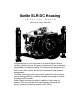
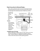
Ikelite SLR-DC Housing i n s t r u c t i o n m a n u a l #6870.40 for Canon EOS 40D Congratulations on your purchase of an Ikelite Digital Camera Housing. Ikelite has over 40 years of experience in the underwater photographic and lighting market. Our products are designed and built in the USA by Ikelite for both the professional and amateur photographer.
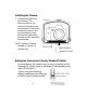
Opening the Housing Lid Snaps have a Lock. To open, push Lid Snap Lock forward and lift as shown. Keep pressure on the Lid Snap so it does not fly open quickly. Some lid snaps have a lot of spring tension once they go over center, have a firm grip on the lid snap. Lid Snaps may be opened one at a time.
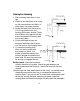
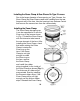
Installing the Camera 1. Remove the back from the housing. The mounting tray for the camera is secured to the housing back. Position the camera and lens on the tray and secure it with the mounting bolt which threads into the camera's tripod socket. NOTE: Strobe ID Switch located on bottom of camera tray. Setting the Conversion Circuitry Strobe ID Switch. On the bottom of the camera tray is a switch for setting the DS Substrobe ID. Set the switch to the Model of DS Substrobe being used, SD125orDS51.
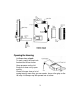
Flash Connection for External Strobes When using an external strobe connect the housings Hot Shoe Connector, slide the connector into the hot shoe of the camera from the back of the camera as shown. Slide the connector forward until it stops. This can be done after the camera is secured with the mounting bolt. Caution: Do not remove External Strobe Connector's waterproof cap unless an external sync is going to be plugged in.
Closing the Housing 1. Place housing face down in your lap. 2. Check to see that there is an o'ring on the housing back and that it is clean and in its proper location. 3. Guide the back onto the housing. The o'ring should touch the housing all the way around. There should be an even gap all the way around between the housing and the housing back. 4. Lift the lid snaps so they are extended and place the lid snap into the hook on the housing back. 5.
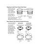
Preparing to Install Zoom Clamp & Gear Sleeve Determine the type of lens being used on the camera. Type 1 Lenses have a lens opening that is NOT larger in diameter than the zoom ring. (Fig. 1). Type 2 Lenses have a lens opening that IS larger in diameter than the zoom ring. (Fig. 2). Zoom Clamps & Gear Sleeves Included with Housing There are 2 different Zoom Clamps and Gear Sleeves provided with the housing. Start with the suggested Zoom Clamp and Gear Sleeve depending on the Type of lens being used.
Installing the Zoom Clamp & Gear Sleeve On the Type 1 Lenses Installing the Zoom Clamp The Zoom Clamp has springs so it can be expanded to fit over the Zoom ring of the lens as shown in (Fig. Q. Install the Zoom Clamp with the extension tabs toward the rear element of the lens. After installing the Zoom Clamp, check that when rotating the Zoom Clamp it rotates the Zoom ring on the lens.
Install the Gear Sleeve After the Zoom Clamp is installed, lower the appropriate Gear Sleeve over the Zoom Clamp aligning the Gear Sleeve ribs with the grooves in the Zoom Clamps extended tabs as shown (Fig. D & E), Note that the ribs of the Gear Sleeve should slide freely in the grooves of the Zoom Clamp.
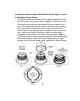
Installing the Zoom Clamp & Gear Sleeve On Type 2 Lenses Due to the larger diameter of lens opening on Type 2 lenses, the Zoom Clamp and Gear Sleeve need to be installed from the rear (bayonet end) of the lens. Use the housings Lens Release Control and remove the camera lens from the camera body. Installing the Zoom Clamp The Zoom Clamp has springs so it can be expanded to fit over the Zoom ring of the lens as shown in (Fig. I).
Installing the Gear Sleeve After the Zoom Clamp is installed. Place the Gear Sleeve in the port opening of the housing (Fig. I). Lower the lens through the Gear Sleeve, aligning the grooves in the Zoom Clamp with the ribs on the Gear Sleeve. Note that the ribs of the Gear Sleeve should slide freely in the grooves of the Zoom Clamp. If the Gear Sleeve does not slide freely, remove any rubber strips on the inside of the Zoom Clamp (Fig. H) or use thinner rubber strips.
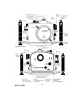
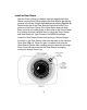
Installing the Port There are two port locks on the front of the housing. (See housing front) Each port lock has a Release Button, lift the release button and slide each Port Lock away from the port opening. In the unlocked position the Release Button will remain in the up position as shown. To prepare the port for installation, remove the port o'ring and lightly lubricate it. The port seal is a side-to-side seal and requires the o'ring to be lightly lubricated for easy installation.
Installing the Port cont. To Remove Port To remove the port lift up on each Release Button and slide the port lock away from the port. Port Seal Inside View If the port is installed before the camera is inserted into the housing, look on the inside of the housings at the port seal. Check to see that the o'ring is properly sealed as shown in figure 1 and not extruded as shown in figure 2. Caution: After installing the port, turn the Zoom Control knob on the housing.
Using External Strobes This housing has Conversion Circuitry built into the camera tray. When used with Ikelite DS Substrobes the Conversion Circuitry provides real Canon eTTL flash exposure with over and underexposure compensation of two f-stops in half-stop increments. The Conversion Circuitry also offers Manual exposure control with 31/2f-stops of under-exposure control in 1/2 stop increments. The Conversion Circuitry is powered by the Ikelite DS Substrobe when connected to the housing with the #4103.
Using External Strobes Cont. Using the Conversion Circuitry (Set Ds substrate to TTL mode) • Mode and Compensation Buttons The Conversion Circuitry default is set to TTL. To switch between TTL and Manual Modes depress both Mode Buttons at the same time and keep then depressed until you see the desired Yellow LED Mode illuminate. • TTL Mode (indicated when the Yellow LED directly below TTL is illuminated). TTL Mode is the default setting.
NOTE: DS Substrobe Up-date may be required. DS50 Substrobes • DS50 Substrobes with a Serial Number below 63,850 can not be updated to operate with the eTTL Conversion Circuitry. • DS50 Substrobes with a Serial Number between 63,850 and 69,999 operate with the eTTL Conversion Circuitry, but require update to provide optimum performance.
Using External Strobes Cont. Using Ikelite Non-DS Substrobes (Substrobe 50, 100A, 200, 400) with this Housing. The Conversion Circuitry is automatically disabled when used with a Non-DS Substrobe. These Substrobes can be used in their manual mode utilizing any power settings provided on the Substrobe. Using Non Ikelite Strobes with this Housing. The Conversion Circuitry is automatically disabled when used with a Non Ikelite Strobe.
Strobe Arms This housing offers two types of arm mounting systems. The top of the rubber handles utilize Ikelite's Quick-Release Arm, available with the SA-100R Arm system. The bottom of the rubber handles have a wing nut that accepts the Ikelite Tray Mount. The Tray Mount comes with the Ikelite SA-125 Arm system and the SA-100T Arm system. Pre-Dive Your System It is recommended that you take the complete system into a swimming pool before use in open water.
Optional Accessories Lead Weight #0906.58 The buoyancy of the system will depend on the size and number of strobes used as well as the weight of the camera. Ideally the system should be slightly negative in the environment in which it will be used. If you need to add weight to the system, an optional lead weight is available. To add the lead weight remove the (2) screws from the bottom of the aluminum tray. Place the lead weight into the pocket of the aluminum tray and reattach. #5512.
Port Information While we have included a list of our ports and a short list of Canon Lenses and port recommendations we suggest visiting our web site for the latest information on lenses and port recommendations. • With the lens on the camera extended to full length, measure from front of camera to face of lens. • Select appropriate based lens type and length. on the port the • Maximum lens diameter accommodated is 8.4cm (3.3") • Maximum lens diameter when using zoom or focus clamp 7.1cm (2.
Ports Continued FLAT PORT For standard, macro, and telephoto lenses. Due to refraction flat ports reduce the angle-of -coverage of a lens and at the same time enlarge the image. This makes the flat port ideal when using standard, macro or zoom lenses to shoot small subjects. Note that if a port is long enough to accommodate the full length of a 1:1 macro lens, the lens may vignette when used at infinity. If access to the lens' full range is desired, then select a dome port instead. FLAT PORT #5501.........
Lens & Port Recommendations Canon Lenses—.—. ------------------- Dome. -------- Flat Port----------Flat Port w/Focus 14mm EF 1:2.8 ................................. 5503(1) 15mm Fisheye ................................. 5503.15 20mm ............................................... 5503 24mm ............................................... 5503 28mm ................................................5503.............. 5501 35mm ...............................................5503.............. 5501 50mm Macro 1:2.
Maintenance The Ikelite Housing should be given the same care and attention as your other photographic equipment, in addition to normal maintenance we recommend that the housing be returned to Ikelite periodically to be checked and pressure tested. 1. Do Not leave the camera and housing in direct sunlight for prolonged periods. Heat may damage the camera. 2. Do Not ship the camera in the housing. 3. Before using the housing, always check the tightness of the set screw in each control knob.
Control Maintenance Ikelite controls are designed to provide years of reliable service with minimal maintenance. 1. Push button controls require no maintenance other than rinsing in fresh water after saltwater use. If a push button control becomes difficult to push or if it sticks when depressed, soak the housing in luke warm fresh water. After a few minutes operate the push button. If this does not correct the problem, return the housing to Ikelite for maintenance. 2. Some of the controls have long shafts.
Some of the controls have a short shaft and cannot be pulled out exposing the shaft for lubrication. In the unlikely event one of these controls sticks or becomes difficult to operate you can remove the control from the housing and lubricate it, or return the housing to Ikelite for maintenance. To remove the control, loosen the set screw in the knob (alien wrench required); remove the knob. If there is salt or dirt build-up on the exposed control shaft, clean the shaft.
General Tips 1. You should completely assemble and test your set-up in a swimming pool before using it in open water. 2. It is a good idea to start each photo dive with a fully charged battery(s) in the camera and strobes. 3. As soon as you enter the water, take a moment and check the housing to see that it is properly sealed. 4. Next, check to see if there are any bubbles on the face of the port. If there are, take your finger and remove them.
Photo Tips 1. The number one rule in underwater photography is eliminate as much water between camera and subject as possible. Get as close as you can to the subject, then use the zoom. If you are using flash, subjects beyond 6 feet (1.8m)will not have much color. 2. Digital cameras have a slight lag time between when you press the shutter release button and the camera actually takes the picture.
Ikelite Limited Warranty All Ikelite products are warranted against any manufacturing defects for a period of one (1) year from the date of purchase. Defective products should be returned prepaid to Ikelite. Ikelite will, at its discretion, repair or replace such products, and will return to customer prepaid. All other claims, of any nature, including but not limited to bulb failure are not covered. Except as mentioned above, no other warranty expressed or implied, applies to this Ikelite product.