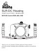
SLR-DC Housing instruction manual 6870.50 Canon EOS 40D, 50D IKELITE Port Lock Thank you for your purchase of Ikelite equipment. Please read this instruction manual completely before attempting to operate or dive with this product.
Table of Contents Product Registration ........................................................P. 3 Package Contents ......................................................P. 3 Preparation ..................................................................P. Parts of the Housing / Size and Weight ..........................P. Initial Camera Setup........................................................P. Opening the Housing ......................................................P. Installing the Camera .........
Product Registration Please take a moment to fill out the online Ikelite Product Registration form at http://www.ikelite.com/forms/regForm.htm. Package Contents - SLR-DC Housing - Aluminum Tray & Dual Handles - Envelope containing tray installation hardware, maintenance kit, and extra control end tips. - Silicone Lubricant - Std. Zoom Clamp & Sleeve Set - #5509.28 Large Diameter Zoom Clamp & Sleeve Set Preparation This product has been water pressure tested at the factory and is depth rated to 200 ft.
Parts of the Housing - Front View WB/Metering Mode Handle AF/Drive Mode LCD Illuminator Zoom Control Main Dial IKELITE AF/ON Port Lock Gear Sleeve Drive Gear Port Opening Shutter Release Lid Snap Aluminum Tray Side View Main Dial Port Lock Gear Sleeve Main Housing O-ring Optional Port AF-ON Shutter Release Camera Tray Port O-ring Camera Mounting Bolt 4 Tray Leveling Screw (factory preset)
Back View Quick Release Button ISO/Flash Exp. Zoom Dial AF-ON 2 3 Lens Release /DOF 4 5 7 1 9 10 11 12 13 8 14 6 Shutter Release 15 16 1. External Strobe Connector and Waterproof Cap 2. Menu 3. Live View (50D only) 4. Optical Viewfinder Port 5. AE/FE Lock 6. AF Point Select 7. Set 8. Quick Control Dial 9. Playback 10. Erase 11. Jump or Info 12. Info or Picture Style 13. Picture Style or Function 14. On/Off 15. Flash Mode “-” Compensation 16. Flash Mode “+” Compensation Size and Weight Width .
Initial Camera Setup - Insert a fully charged battery. Insert memory card (2GB or greater capacity recommended). Set the mode dial to “M” manual. Set shutter speed to 1/60th second or 1/125th second for fast moving subjects. Set aperture to F8 for general photography or F22 for macro photography (close-ups). Set Quality to highest jpeg setting or RAW. Set ISO to 100 and Meter to “center-weighted.” Set Review time to 8 seconds. Set White Balance to Auto “AWB.” Set auto-focus mode to “One Shot.
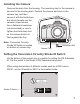
Installing the Camera Remove the back from the housing. The mounting tray for the camera is secured to the housing back. Position the camera and lens on the camera tray, and then secure it with the Hold-down bolt which threads into the CANON camera’s tripod socket. Use a flathead screwdriver EOS 50D (recommended) or coin to tighten the Hold-down bolt so the camera bottom is flush against the tray. Note: Conversion Circuitry Strobe ID Switch is located on bottom of camera tray.
Attaching the Flash Connection for External Strobes When using an external strobe, connect the housing Hotshoe Connector. Slide the Connector into the Hotshoe Mount on the camera from the back of the camera as shown. Slide the Connector forward until it stops. This can be done External Strobe Connector and before or Waterproof Cap after the camera is secured Housing Back with the Hold-down bolt.
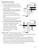
Closing the Housing Housing Back 1. Place housing face down in your lap. 2. Check to see that there is an o-ring on the housing back that is clean and in its proper location. 3. Guide the back onto the housing. The o-ring should touch the housing all the way around. There should be an even gap all the way around between the housing and the housing Housing back. 4. Lift the lid snaps so they are extended and place the lid snap into the corresponding hook on the housing back. 5.
Preparing to Install Zoom Clamp & Gear Sleeve Determine the type of lens being used on the camera. Type 1 Lenses have a lens opening that is NOT larger in diameter than the zoom ring. (Fig. 1). lens opening zoom ring Type 1 lens (Figure 1) bayonet mount Type 2 lens (Figure 2) Type 2 Lenses have a lens opening that IS larger in diameter than the zoom ring. (Fig. 2). Zoom Clamps & Gear Sleeves Included with Housing There are 2 different Zoom Clamps and Gear Sleeves provided with the housing.
Installing the Zoom Clamp & Gear Sleeve On the Type 1 Lenses The Zoom Clamp has springs so it can be expanded to fit over the Zoom Ring of the lens - figure C, page 11. Install the Zoom Clamp with the extension tabs toward the rear element of the lens. After installing the Zoom Clamp and Gear Sleeve - figures D & E, page 12, install the Lens Port and rotate the Zoom Ring on the lens.
Type 1 Lenses (cont.
Installing the Zoom Clamp & Gear Sleeve On Type 2 Lenses Due to the larger diameter lens opening on Type 2 lenses, the Zoom Clamp and Gear Sleeve need to be installed from the rear (bayonet end) of the lens. Use the housing Lens Release Control and remove the camera lens from the camera body, after the camera and lens have been installed in the housing. Place the Gear Sleeve in the housing opening as shown. Install the black Zoom Clamp on the Lens Zoom Ring and lower the lens into the housing opening.
Installing Zoom Clamp/Sleeve on Type 2 Lenses (cont.) Before installing the lens port and checking operation, make sure the teeth on the Gear Sleeve mesh with the teeth on the housing Drive Gear, shown below. When the port is installed, pages 15 & 16, it will lock the Gear Sleeve in place. After installing the port, rotate the housing Zoom Control Knob to see that the Gear Sleeve is properly rotating the Lens Zoom ring.
Installing the Port There are four port locks on the front of the housing, see figure G, page 14. Each port lock has a Release Button. Lift the release button and slide each Port Lock away from the port opening. In the unlocked position, the Release Button will remain in the up position as shown. Port Lock Release Button Locked Position Lift Release Button to Unlock Pull Back to Disengage Port To prepare the port for installation, remove the port o-ring and lightly lubricate it.
Installing the Port (cont.) To Remove Port To remove the port, lift up on each Release Button and slide the port lock away from the port. Port Seal Inside View If the port is installed before the camera is inserted into the housing, look from the inside of the housing at the port seal. Check to see that the o-ring is properly seated as shown in figure 1 and not extruded as shown in figure 2. Fig. 1 Fig. 2 Caution: After installing the port, turn the Zoom Control knob on the housing.
Housing Conversion Circuitry This housing has Conversion Circuitry built into the camera tray, page 7. When used with Ikelite DS Substrobes, the Conversion Circuitry provides real Canon eTTL flash exposure with over and underexposure compensation of two f-stops in half-stop increments. The Conversion Circuitry also offers 8 manual power settings in 1/2 stop increments and is powered by the Ikelite DS Substrobe when connected to the housing with the #4103.51 single or #4103.52 dual sync cord.
DS50 and DS125 Substrobe Compatibility - - Older DS50 Substrobes with Serial Number below 63,850 can NOT be updated to operate correctly with the latest TTL conversion circuitry. Older DS50 Substrobes with Serial Number between 63,850 and 69,999 require upgrade of electronics to operate. Cost of update depends on strobe circuitry. Strobe must be returned to Ikelite for evaluation to provide an estimate of upgrade cost.
Usage Pre-Dive Your System It is recommended that you take the complete system into a swimming pool before use in open water. This will give you a chance to become familiar with the handling and operation of your housing and strobe(s). As soon as you enter the water, take a moment and check the housing to see that it is properly sealed. Next, check to see if there are any bubbles on the face of the port. If there are, take your fingers and remove them.
Troubleshooting Problem Solution Push buttons or controls are sticky and hard to operate - Remove the camera and rinse the closed housing in fresh water. Vigorously press each push button in and out several times to release any trapped saltwater or debris. - Press a sticky push button all the way in and place a small amount of lube on the small end of the push button shaft at it’s base. Release and operate the push button several times to distribute the lube.
Problem Solution Camera does not take a picture - Install a fully charged battery. - A housing control is engaging a camera function and will not allow the shutter to fire. - There is not enough available light for the camera to properly focus. Add a focusing light or strobe with a built-in focusing light to your system. - Select a center focus point in your camera menu. Housing is hard to close - Make sure the camera is mounted properly on the camera tray and housing controls are out of the way .
Replacement Parts 0132.61 Spare Main Housing O-ring 0105 Spare Port-to-Housing O-ring 5020 Silicone Lubricant in 4 1cc Tubes 5512.69 O-ring Kit with Main O-ring, Port O-ring, & 1cc Lubricant 0333.6 Tray Mounting Screw 12-24 x 1/2 in. Stainless 0212.12 1/4 in. Shoulder Washer for 12-24 Screw 9104.5 Waterproof Bulkhead Cap 0200.
Maintenance Control Maintenance - - - Ikelite controls are designed to provide years of reliable service with minimal maintenance. Push button controls require no maintenance other than rinsing in fresh water after saltwater use. If a push button control becomes difficult to push or if it sticks when depressed, soak the housing in luke warm fresh water. After a few minutes, operate the push button. If this does not correct the problem, return the housing to Ikelite for maintenance.
Diagram A Housing Gland Control Shaft Tighten set screw down against this flat area when replacing the knob.
Housing Maintenance - - - - Your Ikelite Housing should be given the same care and attention as your other photographic equipment. In addition to normal maintenance, we recommend your housing be returned to Ikelite (every 2-3 years or 50 dives), to be checked and pressure tested. Do Not leave the camera and housing in direct sunlight for prolonged periods. Heat may damage the camera. Do Not ship the camera in the housing.
Photo Tips - - - - - - - 26 The number one rule in underwater photography is to eliminate as much water between the camera and subject as possible. Get as close as you can to the subject, then use the zoom. If you are using flash for still photos, subjects beyond 6 feet (1.8m) will not have much color regardless of strobe power. Photograph in clear water; do not stir up the sand or silty bottom.
NOTE: To shoot photographs closer than 2 feet (0.6m), we recommend using an external strobe such as the DS51 or DS161. An external strobe can be positioned so nothing blocks the light path between the strobe and the subject. Storing the Housing When the housing is going to be stored for a prolonged period it should be soaked in a mild soap solution, rinsed, and dried thoroughly. Remove the back and port from the housing.
Returning Products for Service Ikelite is most interested in performing any service to ensure that all products perform as intended. Evidence of purchase date must be provided to obtain warranty service. No prior authorization is required. You may return directly to Ikelite or through your dealer. Please include a brief description of the problem, any relevant e-mail correspondence, and/or instructions on requested service.