Reach Ins Installation, Operation and Maintenance Manual Please read this manual completely before attempting to install or operate this equipment. Notify carrier of damage! Inspect all components immediately. IMPORTANT INFORMATION READ BEFORE USE PLEASE SAVE THESE INSTRUCTIONS! See page 2.
Service and Installation Manual CONTENTS RECEIVING & INSPECTING EQUIPMENT .................................................................................. 2 SPECIFICATIONS .......................................................................................................................................... 3 INSTALLATION .................................................................................................................................... 4 OPERATION…......................................
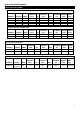
Service and InstallationManual SPECIFICATIONS SOLID DOOR REFRIGERATORS STORAGE CAPACITY MODEL# V/Hz/Ph AMPS HP Cu-ft KB27R 115/60/1 6 23 3/8 SHELF CAPACITY Sq-ft 14.0 3200 CHARGE OZ 12.0 BTU SHIP WEIGHT NEMA LBS PLUG 350 5-15P KB54R 115/60/1 9 49 1/2 28.1 5800 18.7 518 5-15P KB81R 115/60/1 10 72 3/4 42.1 7625 21.2 669 5-15P GLASS DOOR REFRIGERATORS STORAGE CAPACITY MODEL# V/Hz/Ph AMPS HP Cu-ft KB27RG 115/60/1 6 23 3/8 KB54RG 115/60/1 9 49 1/2 SHELF CAPACITY Sq-ft 14.
Service and Installation Manual INSTALLATION Location Units represented in this manual are intended for indoor use only. Be sure the location chosen has a floor strong enough to support the total weight of the cabinet and contents. A fully loaded unit can weigh as much as 1500 pounds. Reinforce the floor as necessary to provide for maximum loading. For the most efficient refrigeration, be sure to provide good air circulation inside and out.
Service and InstallationManual OPERATION Do not throw items into the storage area. Failure to heed these recommendations could result in damage to the interior of the cabinet. CAUTION Refrigerated cycle Refrigerators: During the refrigeration cycle, the evaporator fans will run continuously even when one or more doors are open. The door switch will activate the lights when opened. 1. Every 6 hours, the unit will turn off and to allow the evaporator coil to defrost.
Service and Installation Manual 1.1 Function of LEDS LED MODE ON Flashing FUNCTION Compressor enabled ON -Programming Phase (flashing with - Anti-short cycle delay enabled Defrost enabled - Programming Phase (flashing with - Drip time in progress Fans enabled Flashing Fans delay after defrost in progress. ON An temperature alarm happened ON Flashing ) ) 2. MAIN FUNCTIONS 2.1 HOW TO SEE THE SETPOINT 1. Push and immediately release the SET key: the display will show the set point value. 2.
Service and InstallationManual MAINTENANCE DANGER The unit must be turned OFF and disconnected from the power source whenever performing service, maintenance functions or cleaning the refrigerated area. Refrigerators and Freezers The interior and exterior can be cleaned using soap and warm water. If this isn't sufficient, try ammonia and water or a nonabrasive liquid cleaner. When cleaning the exterior, always rub with the "grain" of the stainless steel to avoid marring the finish.
Service and Installation Manual MAINTENANCE Cleaning solutions need to be alkaline based or non-chloride based. Any cleaner containing chlorides will damage the protective film of the stainless steel. Chlorides are commonly found in hard water, salts, and household and industrial cleaners. If cleaners containing chlorides are used, be sure to rinse and dry thoroughly. Routine cleaning of stainless steel can be done with soap and water.
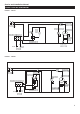
Service and Installation Manual ELECTRICAL DIAGRAM MODEL:KB27R MODEL:KB54R 9
Service and Installation Manual ELECTRICAL DIAGRAM MODEL:KB81R N L PLUG OVERLOAD PROTECTOR EVAP FAN CONTACTOR LAMP M M CONDENSEN FAN COMPRESSOR THERMOSTAT DISPLAY CURRENT RELAY ROOM EVAP SENSOR DOOR SWITCH MODEL:KB27RG N L OVERLOAD PROTECTOR EVAP ROOM SENSOR 10 M LED DRIVER THERMOSTAT DISPLAY EVAPORATOR FAN PLUG DOOR SWITCH CONDENSEN LAMP M COMPRESSOR FAN CURRENT RELAY LAMP SWITCH STARTING CAPACITOR
Service and Installation Manual ELECTRICAL DIAGRAM MODEL:KB54RG N L M THERMOSTAT DISPLAY LAMP LAMP M EVAP CONDENSEN FAN COMPRESSOR CURRENT RELAY LAMP SWITCH ROOM OVERLOAD PROTECTOR CONTACTOR LED DRIVER EVAPORATOR FAN PLUG DOOR SWITCH STARTING CAPACITOR SENSOR MODEL:KB27F EVAP LAMP CONDENSEN FAN THERMAL CUT-OFF COMPRESSOR M PIPE HEATER M DOOR SWITCH THERMOSTAT DISPLAY ROOM OVERLOAD PROTECTOR CONTACTOR DEFROST HEATER EVAP FAN N L PLUG CURRENT RELAY STARTING CAPACITOR SENSOR
Service and Installation Manual ELECTRICAL DIAGRAM MODEL:KB54F OVERLOAD PROTECTOR N L DEFROST HEATER CONTACTOR THERMAL CUT-OFF M THERMOSTAT DISPLAY MIDDLE FRAME HEATER CONTACTOR DOOR FRAME HEATER LAMP PIPE HEATER EVAP FAN PLUG CONDENSEN FAN M CURRENT RELAY STARTING CAPACITOR EVAP ROOM COMPRESSOR RUN CAPACITOR SENSOR MODEL:KB81FDV CONTACTOR OVERLOAD PROTECTOR Y w X POWER PLUG THERMAL CUT-OFF M EVAP ROOM SENSOR 12 M MIDDLE FRAME HEATER MIDDLE FRAME HEATER DOOR FRAME HEATER LA
Service and InstallationManual WIRING DIAGRAM MODEL: KB27R 13
Service and InstallationManual WIRING DIAGRAM MODEL: KB27RG 14
Service and InstallationManual WIRING DIAGRAM MODEL: KB27F 15
Service and Installation Manual WIRING DIAGRAM MODEL: KB54R 16
Service and Installation Manual WIRING DIAGRAM MODEL: KB54RG 17
Service and Installation Manual WIRING DIAGRAM MODEL: KB54F 18
Service and Installation Manual WIRING DIAGRAM MODEL: KB81R 19
Service and InstallationManual WIRING DIAGRAM MODEL: KB81FDV 20
Service and Installation Manual IKON WARRANTY Two Year Parts & Labor Warranty MVP Group (IKON) warrants, to the original purchaser, all of its new equipment to be free from defects in material and workmanship, under normal use and maintenance service, for a period of two (2) years from the date of original purchase or 15 months after shipment date from the manufacturer, whichever occurs first.