
User Manual


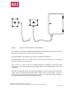


Table Of Contents

I N D E X
Pg.
CONFORMITY DECLARATION.................................................................................... 3
1 DESCRIPTION .......................................................................................................... 4
2 SAFETY PRECAUTIONS......................................................................................... 5
2.1 What you must do .............................................................................................. 5
2.2 What you must not do........................................................................................ 5
3 INSTALLATION ....................................................................................................... 6
3.1 The BC60K battery charger............................................................................... 6
3.2 Receiver ............................................................................................................. 7
3.3 Starting-up ....................................................................................................... 11
3.4 Spurious Disturbance....................................................................................... 13
4 USE...........................................................................................................................14
5 HOW TO ACCESS TO THE HOIST CONDITION MONITORING UNIT IN
RADF13 SYSTEM. SERVICE MODE. ..................................................................15
5.1 General Description of Service Mode .............................................................15
5.2 Entering the Service mode............................................................................... 15
5.3 Keys for moving within the Menus. ................................................................16
5.4 Switching from Tared Load to Actual Load.................................................... 16
5.5 Resetting the Tared Load................................................................................. 16
5.6 Exiting Service mode....................................................................................... 17
5.7 Messages originated in the receiver.................................................................17
6 MAINTENANCE ..................................................................................................... 18
6.1 Precautions....................................................................................................... 18
6.2 Preventive maintenance ................................................................................... 18
6.3 Locating Break-downs..................................................................................... 19
7 Drilling pattern sheet. ............................................................................................... 20
INDEX OF FIGURES
Figure 1 Battery charger BC60K ................................................................................6
Figure 2 Receiver Box dimensions ............................................................................. 7
Figure 3 Receiver to Power Electric Circuit connection............................................. 8
Figure 4 Connection diagram for RADS11................................................................. 9
Figure 5 Connection diagram for RADF13............................................................... 10
Figure 6 RADS11 and RADF13 transmitters ........................................................... 12
Figure 7 Entering the Service mode.......................................................................... 15
Figure 8 LCD Display in Service Mode.................................................................... 16
Figure 9 Pushbutton as a Key board for Hoist Condition Monitoring Unit.............. 16
Figure 10 LCD representing Tared Load .................................................................... 16
RADS11 and RADF13 Users Manual ver1.2.doc
KCI Hoists Corp. reserves the right to modify this information without prior notification.
Page 2 of 20