SHUTTER MOUNTED EXHAUST FAN Models: ILG8SF10V(APB-10A)/ILG8SF12V(APB-12A) ILG8SF16V(APB-16A)/ILG8SF18V(APB-18A) ILG8SF18S(APB-18B)/ILG8SF20V(APB-20A) ILG8SF24V(APB-24A)/ILG8SF30S(APB-30B) ILG8SF36S(APB-36B) OWNER'S MANUAL PLEASE READ AND SAVE THESE INSTRUCTIONS 1
PLEASE READ AND SAVE THESE INSTRUCTIONS. READ CAREFULLY BEFORE ATTEMPTING TO ASSEMBLE, INSTALL, OPERATE, OR MAINTAIN THE PRODUCT DESCRIBED. PROTECT YOURSELF AND OTHERS BY OBSERVING ALL SAFETY INFORMATION. FAILURE TO COMPLY WITH INSTRUCTIONS COULD RESULT IN PERSONAL INJURY AND/OR PROPERTY DAMAGE! RETAIN INSTRUCTIONS FOR FUTURE REFERENCE. BEFORE YOU BEGIN WARNING! Installation, troubleshooting, and replacement of parts are to be performed only by authorized service technicians.
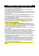
GENERAL SAFETY INSTRUCTIONS Fans are UL/cUL Listed, Standard 705. 1. Do not depend on any switch as the sole means of disconnecting power when installing or servicing the fan. 2. Always disconnect, lock-out, and tag-out power source before installing or servicing. Failure to disconnect power source can result in fire, shock, or serious injury. 3. Motor will restart without warning after thermal protector trips. Do not touch operating motor; it may be hot enough to cause injury. 4.
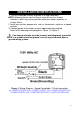
INSTALLATION INSTRUCTIONS INSTALLATION INSTRUCTION 1. The unit should be securely mounted in a rigid framework. NOTE: Allowing the fan frame to flex or move will result in excess vibrations, which may cause possible premature motor, propeller, or shutter failure. 2. Install any auxiliary components such as thermostats, switches, or speed controls. 3. Connect power to the motor using an approved wiring method. Refer to the following wiring diagrams: Figure 1 & Figure 2.
Figure 2: Wiring Diagram - Single speed. 115-volt connection.
GENERAL SPECIFICATIONS Power source Mounting Position Frame Material Shutter Blade Material Propeller Material Agency Compliance 115V, 60Hz Vertical Galvanized Steel Aluminum Alloy Aluminum Alloy and Galvanized Steel UL/cUL 705 Dimensions (Inches) Figure 3 Prop. Dia.
Performance Sones @ Bearing 0.0" SP @ Type 5' Prop. Dia. Nom. HP Amps Nom. RPM ILG8SF10V (APB-10A) 10" 1/25 0.55 1550 Sleeve ILG8SF12V (APB-12A) 12" 1/20 0.60 1625 ILG8SF16V (APB-16A) 16" 1/20 0.85 ILG8SF18V (APB-18A) 18" 1/15 ILG8SF18S (APB-18B) 18" ILG8SF20V (APB-20A) MODEL CFM Air Delivery @ Static Pressure Shown 0.00" 0.125" 0.25" 6.19 600 354 N/A Sleeve 5.9 772 418 N/A 1550 Ball 6.39 1200 416 180 0.85 1075 Ball 7.4 1736 1108 N/A 1/4 3.
MAINTAINANCE 1. Disconnect power source before servicing. 2. Periodically clean off accumulated dirt from the propeller, guard, motor, and shutter. Do not depend on any switch as the sole means of disconnecting power when installing or servicing. If power disconnect is not visible, utilize OSHA Lock out/Tag out procedure. Failure to do so may result in fatal electrical shock. Employ proper lock-out/tag-out procedures when performing maintenance.
iLIVING USA 239 Harbor Way South San Francisco, CA 94080 Tel: 800-317-1688 Email: service@ilivingusa.com Like us on Facebook: https://www.facebook.com/ilivingusa/ Follow us on Twitter: @iLIVINGUSA Check out our website: www.ilivingusa.