U ser Instructions, Installation, maintenance for •COOKERS• Majestic Maj estic • Pr o f e s s i o n a l • QQuuaa d r a C o o k e r s c h a racteristics These warnings refer to different models of cookers. Be sure that you have correctly identifiedthe model that you possess (see the data plate). MODEL DIMENSIONS UP60 UP76 UM76 UP90, UPD90 UM90 UPD100 UQM100 UMD100 UP120,UPD120 UM120 UP150 UM150 23 29 29 35 35 39 39 39 47 47 59 59 cod.
IM P ORTA NT - P LEASE READ AND FOL L OW • Before beginning, please read these instructions completely and carefully. • Do not remove permanently affixed labels, warnings, or plates from the product. This may void the warranty. • Please observe all local and national codes and ordinances. • Please ensure that this product is properly grounded. • The installer should leave these instructions with the consumer who should retain for local inspector’s use and for future reference.
Keeping appliance area clear and free from combustible materials, gasoline and other flammable vapors and liquids. I M P O R TA N T I N S T R U C T I O N All Appliances: Do Not Leave Children Alone - Children should not be left alone or unattended in area where appliance is in use. They should never be allowed to sit or stand on any part of the appliance. Do not store items of interest to children above or at the back of this appliance, as they could climb on the appliance to reach items and be injured.
I N S TA L L AT I O N I N S T R U C T I O N S This appliance shall only be installed by an authorized person. This appliance shall be installed in accordance with the manufactures installation instructions, IMPORTANT: this appliance must be installed in accordance with the norms in force of the country concerned. The installation of this appliance must conform to local codes and ordinances. In the absence of local codes.
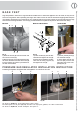
BASE FEET Legs are packed in carton box. Legs should be installed near to where the appliance is to be used, as they are not secure for long transit. After unpacking the range, raise it about a foot to remove the bottom shipping skid. Keep the unit raised to permit legs to be screwed into our couplings and lower it gently to keep any undue strain from the legs and internal mounting hardware. It is strongly recommended that a pallet or lift jack be used rather than tilting.
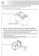
B AC KGU A R D I NS TA L L AT IO N IN S T RU C T IO N Please follow the following installation instructions in sequence: 1. install base feet (see proper instruction Fig.3 ) 2. Place the backguard and fix it from bottom side with the two screw as shown in figure below. Figure 3 ANTI-TIP STABILITY DEVICE INSTALLATION INSTRUCTIONS 1. The anti-tip bracket have to be attached to rear wall, as show in Fig.4, before backguard installation.
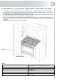
P R O X I M I T Y T O S I D E C A B I N E T I N S TA L L AT I O N 1. This range may be installed directly adjacent to existing [33 15/32” - 36 20/32”] high base cabinets. IMPORTANT: The top border of the worktop should be at the same level of the adjacent cabinets counter top. This may be accomplished by raising using the adjustment spindles on the legs. 2. The range CANNOT be installed directly adjacent to sidewall, as cabinets, appliances, or other side vertical surface above 36 20/32” high.
ELECT RICA L CONNEC T IO N The appliance shall be connected to a single phase electric line rated at 120/208Vac or 120/240Vac and 60Hz frequency. The appliance is equipped at the factory with a flexible hose . Inside the flexible hose you have 4 cables: grenn cable must be connected to the ground, white cable (NEUTRAL), red en black cables: supply wire (L1 – L2).
P ER FORMA NCE CHE CKL IS T All bur ners are tested before leaving the factory. There are no adjustments for the bur ners if connected according to the information on the rating plate. Check each bur ner for proper operations. Flames should be blue in all settings. If service is required, contact your dealer for the name of their authorized service agency. Gas conversions and initial installation are not responsibility of the manufacturer. The installer should carry out the following performance checks.
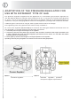
AD APTATI ON OF THE P RE S S U RE RE G U L AT O R FO R U S E WITH DI FFER E NT T Y PE O F G AS The pressure regulator supplied with the appliance is a convertible type pressure regulator for use with Natural Gas at a nominal outlet pressure of 5”w.c. or LP gas at a nominal outlet pressure of 10”w.c. and it is pre-arranged from the factory to operate with one of these gas/pressure as indicated in the pre-arranging labels affixed on the appliance, package and Instruction booklet.
CHANGING THE INJECTORS AND ADJUSTING THE AIR TABLE 2 Bur ner Gas INPUT RATE [Btu/h] ORIFICE SIZE (1/100) mm SIMMER RATE [Btu/h] PRIMARY AIR OPENING BY-PASS ORIFICE SIZE (1/100)mm SR NATURAL (A) 7000 120 2100 Open Adj.* R NATURAL (A) 10500 145 3200 Open Adj.* Fish Kettle NATURAL (A) 10500 145 3600 Open Adj.* TC NATURAL (A) 15500 180 5600 Open Adj.* D ual NATURAL (A) 15500 165+68 8000 15 (exter nal) / Open (inner ring) Adj.
A1) Burners of the hob 1. Remove the grill, the caps and the burners from the worktop. 2. Lift the worktop. 3. Unscrew the screw “F” and remove the pipe “R”. 4. Unscrew the injectors (U) and replace them with those suitable for the gas used, supplied with the cooker. See TABLE 2. 5. The air is adjusted by means of the pipe “R” according to the value “X” given in TABLE 2 for the primary air opening. Once regulation has been completed, secure the pipe ”R” with the screw “F”.
A D JU ST IN G THE MI NI MU M G A S F L O W When installing the cooker you must check that the minimum gas flow of the burners on the hob and in the oven is correctly regulated. If the type of gas is changed it is indispensable to adjust the minimum flow. The regulating procedure is as follows. A) Burners on the hob (fig. 13) 1. Light one burner at a time and turn the flame up to maximum. 2.
O VEN CL E A NI NG A ND C A RE It is advised to clean the oven after each use. The dirt comes off more easily, preventing it from being burnt repeatedly at high temperatures. Wait until the chamber is lukewarm. Remove all the extractable parts and wash them separately in hot water and non abrasive detergent. The cooking chamber can be cleaned with a soft cloth soaked in a solution of lukewarm water and ammonia; then rinse and dry. Do not use abrasive or corrosive detergents as they may damage the oven.
Self-cleaning panels If the oven is equipped with self-cleaning catalytic panels, at normal cooking temperatures (430°F) the catalytic enamel favours the transformation of splashes of fat into a light powder residue. This powder may be removed with a damp cloth once the oven has cooled. In this way the enamel surface remains porous and ensures maximum yield of the panels.
U S ER M A NUA L IMPO RTANT: keep children away from the appliance when it operates. The oven door becomes very hot. Safety rules do not always cover any type of accident. The appliance must not be used for heating purposes. If other electric appliances are connected to outlets placed near the appliance, make sure that the connection cables will not be trapped in the oven door while operating.
Figure 23 Figure 24 Figure 25 17
U S E OF THE E L ECTR O N IC P RO G RAM M E R REMARK: To know what the electronic programmer drive see ELECTRONIC PROGRAMMER TABLE (at the end of the booklet). ATTENTION: DO NOT USE ELECTRONIC PROGRAMMER WHEN VENTILATED GAS FUNCTION IS SELECT. A 1. FUNCTIONS: cooking time - end of cooking - clock - timer - manual operation 2. DISPLAY - symbols indicating functions in progress: duration and manual functions = pot symbol automatic programme = “A” minute minder = bell symbol 3.
8. SEMI-AUTOMATIC FUNCTION WITH END OF COOKING TIME Choose the function end of cooking ( and the pot symbol button) and set the final time with the +/- buttons. The symbols “A” appear. The oven is switched on. When the time coincides with the set time the oven is switched off and the pot symbol disappears. The buzzer then sounds. The symbol “A” starts to flash. 9. AUTOMATIC FUNCTION WITH COOKING TIME AND END OF COOKING Choose the function cooking time and set the required time with the +/- buttons.
U S E OF THE MULTI FU N C T IO N O V E N Turn the selector knob (S) and choose the function. Select the desired temperature from 100˚F to 500˚F turning the thermostat (T). If your oven is fitted with a programmer then you have to switch it on. Oven light To switch the light off/on, press the selector knob (S). When selector knob is set in (0) position, light is not working. 1 Pizza cooking Pizza function suitable when cooking pizza, bread and scones.
USE O F T HE S TATI C OV E N 1 Upper & lower elements This operates like a conventional electric oven and can be used accordingly. 2 Upper element Especially suitable for browning and to add the finishing touches of colour to different dishes. We suggest this setting when cooking hamburgers, pork outlets, steaks etc. 3 Lower element As the heat comes from the lower element, this setting is particularly suitable for pastry and cakes e.g. flans, pizzas, biscuits, fruit cakes etc.
HOW TO USE THE GAS OVEN WITH GAS GRILL 1 Selecting ventilated gas function Turn the knob (A) and select the “ventilated cooking gas”. Then turn the knob (G) and select the desired temperature. The ignition of the oven burner takes place automatically after a few seconds. If this does not happen, switch off and repeat the operation. 2 Electric lighting of the gas oven Turn the knob (A) and select the “static cooking gas”. Then turn the knob (G) and select the desired temperature (150 to 500 ° F).
WARNING The effect that top burner flame size should be adjusted so it does not extend beyond the edge of the cooking utensil. This is an instruction based on safety considerations. Figure 30 USE O F T HE COUP FEU The large “Coup feu” solid cast iron plate made of concentric rings allows you to rest the pan (or even several pans) directly on the surface (Fig. 32, 33 ). It is heated by means of a gas burner (Fig. 31).
I NST RUCTI ONS FOR U S E O F T H E G AS F RY- T O P The Fry-Top is composed of a special stainless steel plate (20/64” thick), specially designed to have temperatures evenly distributed over the whole surface so that it may be exploited to the full. The plate also has hygienic advantages. Another merit is the high heat accumulation of the plate, with very low heat loss.
G A S BARBE CUE Replace the burner cap A with the protected barbecue burner cap B. Before positioning the barbecue plate, ensure that the burner cap has been fitted correctly and test lighting of the burner. To use the appliance, light the flame below the plate by means of the corresponding knob (see “Lighting the burners”) and ensure that the flame is burning. Leave the knob in this position for about 10 minutes at the most and wait for the plate to heat up.
FAN OVE N COOKI NG C H A RT MEATS TEMPERATURE [°F ] POSITION Roast beef 340 - 360 2–3 40 - 50 Roast ox 340 – 370 2–3 40 – 60 Roast veal 320 – 360 2–3 65 - 90 Roast lamb 285 – 320 2 100 – 130 Rare roast beef 360 -370 2–3 40 - 45 Roast hare 340 - 360 2–3 30 - 50 Roast rabbit 320 - 360 2 80 - 100 Roast turkey 320 – 360 2 160 – 240 Roast goose 320 – 370 2–3 120 - 160 Roast duck 340 – 360 2-3 100 – 160 Rare roast beef 360 2–3 70 - 90 FISH 320 - 360 2–3 15 – 25 F
NATURAL CONV E CTI ON O V E N C O O K IN G C H ART MEATS TEMPERATURE [°F] POSITION Roast beef 440 2–3 60 - 80 Roast ox 450-500 2–3 50 – 60 Roast veal 440 2–3 60 - 80 Roast lamb 440 2 40 – 50 Rare roast beef 450 2–3 50 – 60 Roast hare 450-500 2–3 40 - 50 Roast rabbit 450-500 2 40 - 50 Roast turkey 450-500 2 50 – 60 Roast goose 440 2–3 60 - 70 Roast duck 450-500 2-3 45 – 60 Rare roast beef 450-500 2–3 40 – 45 FISH 390 - 440 1–2 15 – 25 Fruit cake 440 2 35
ELECT RICA L S KE TCH E S KEYS KEYS KEYS 00 BLACK K8 EARTH WIRE ROTISSERIE R1 UPPER HEATING ELEMENT 11 BROWN K9 EARTH WIRE COOLING FAN R2 LOWER HEATING ELEMENT 22 RED K10 EARTH WIRE SELECTOR R3 GRILL HEATING ELEMENT 33 WHITE K11 EARTH WIRE OVEN THERMOSTAT R4 CIRCULAR HEATING ELEMENT 44 YELLOW K12 EARTH WIRE PROGRAMMER R5 BARBECUE HEATING ELEMENT 55 YELLOW-GREEN K13 EARTH WIRE GRILL RE ENERGY REGULATOR 66 GREY K14 EARTH WIRE EL.
MULTIFUNCTION MODELS ONLY Big Solid Top Burner 29
U P 90MP 30
UP9 0VG 31
U P D100FMP 32
UPD 90VG 33
U P 120SMP 34
UP1 20VG 35
U P 150MP 36
UM 15 0SVG 37
U P 90VGG 38
UPD 90VGG 39
U P 120VGG 40
UP1 50SVGG 41
ELECTR I CA L A ND G AS PO W E R TA BL E 70 VGG 90 VGG 0,1 1 1 1 1 1 1 1 1 1 1 1 1 1 1 1 1 1 1 1 1 1 1 1 1 1 1 1 1 1 1 1 1 1 1 1 1 1 1 1 1 1 1 1 1 1 1 1 1 1 1 1 1 1 1 1 1 1 1 1 1 1 1 1 1 1 1 1 1 1 1 1 1 1 1 1 1 1 1 1 1 1 1 1 1 1 1 1 1 1 1 1 1 1 1 1 1 1 1 1 1 1 1 1 1 1 1 1 1 1 1 1 1 1 1 1 1 1 1 1 1 1 1 1 1 1 1 1 1 1 1 1 1 1 1 1 1 1 1 1 1 1 1 1 1 1 1 1 42 1 1 1 1 1 1 1 1 1 1 1 1 1 1 1 1 1 1 1 1 1 1 1 1 1 1 1 1 1 1 1 1 1 1 1 1 1 1 1 1 1 1 1 1 1 1
TC FK TP1 TP2 90 VG 60 VG 60 VGG 70 VG 70-90 GG 90 MULTIF 60 MULTIF 70 MULTIF 40 STATICO 30 STATICO 90 VENT 60 VENT 70 VENT 60 VGG 70 VGG 90 VGG 15500 10500 8500 8500 15000 11500 9000 15000 13500 3,7 3,7 3,7 2 1,8 2,5 1,8 2,5 0,1 0,1 0,1 1 1 1 1 1 1 1 1 1 1 1 1 1 1 1 1 1 1 1 1 1 1 1 1 1 1 1 1 1 1 1 1 1 1 1 1 1 1 1 1 1 1 1 1 1 1 1 1 1 1 1 1 1 1 1 1 1 1 1 1 1 1 1 1 1 1 1 1 1 1 1 1 1 2 3 3 3 3 3 3 3 3 3 3 3 3 2 2 2 2 2 2 3 3 3 3 3 3 2 2 2 3 3 3 3 3 3 2 2 2 3 3 3 3 3 3 2
90 VGG 1 1 1 1 1 1 1 1 1 1 1 1 1 1 1 1 1 1 1 1 1 1 1 1 1 1 1 1 1 1 1 1 1 1 1 1 1 1 1 1 1 1 1 1 1 1 1 1 1 1 1 1 1 1 1 1 1 1 1 1 1 1 1 1 1 1 1 1 1 1 1 1 1 1 1 1 1 1 1 1 1 1 1 1 1 1 1 1 1 1 1 1 1 1 1 1 1 1 1 1 1 1 1 1 1 1 1 1 1 1 1 1 1 1 1 1 1 1 1 1 1 1 1 1 1 1 1 1 1 1 1 1 1 1 1 1 1 1 1 1 1 1 1 1 1 1 1 1 1 1 1 1 1 1 1 1 44 1 1 1 1 1 1 1 1 1 1 1 1 1 1 1 1 1 1 1 1 1 1 1 1 1 1 1 1 1 1 1 1 1 1 1 1 1 1 1 1 1 1 1 1 1 1 1 1 1 1 1 1 1 1 1 1 1 1 1 1 1
DUAL Fk TP1 TP2 TC 90 VG 60 VG 60 VGG 70 VG 70-90 GG 90 MULTIF 60 MULTIF 70 MULTIF 40 STATICO 30 STATICO 90 VENT 60 VENT 70 VENT 60 VGG 70 VGG 90 VGG 15500 10500 8500 8500 8500 15000 11500 9000 15000 13500 3,7 3,7 3,7 2 1,8 2,5 1,8 2,5 0,1 0,1 0,1 1 1 1 1 1 1 1 1 1 1 1 1 1 1 1 1 1 1 1 1 1 1 1 1 1 1 1 1 1 1 1 1 1 1 1 1 1 1 1 1 1 1 1 1 1 1 1 1 1 1 1 1 1 1 1 1 1 1 1 1 1 1 1 1 1 1 1 1 1 1 1 1 1 2 3 3 3 3 3 3 3 3 3 3 3 3 2 2 2 2 2 2 3 3 3 3 3 3 2 2 2 3 3 3 3 3 3 2 2 2 3
GAS POWER TOTAL GAS POWER [Btu] TOTAL ELECTRICAL POWER [Kw] 81000 3,8 1 81000 3,6 1 90000 2,1 1 90000 1,9 90 VGG 70 MULTIF 3,7 1 70 VGG 60 MULTIF 3,7 3,7 0,1 90 MULTIF 3,7 0,1 69500 0,1 70-90 GG 13500 98000 60 VGG 70 VG 15000 1 2 70 VENT 60 VGG 9000 2 3 0,1 60 VG 11500 3 1 2,5 90 VG 15000 1 UM906DDMP_UM(T/CA)906DDMP 2,5 60 VENT TC 8500 UM906DDVGG_UM(T/CA)906DDVGG 84500 90 VENT TP2 8500 1 1,8 TP1 8500 2 2,5 FK 10500 3 30 STATICO DUAL 15500 1 40 STAT
UPS(F/L/W/N/S)120FDDMP 1 3 2 1 UMS1207DDVG_UMTS1207DDVG_UMCSA1207DDVG 1 3 2 1 1 UMS1207DDVGG_UMTS1207DDVGG_UMCSA1207DDVGG 1 3 2 1 1 UMS1207DDMP_UMTS1207DDMP_UMCSA1207DDMP 1 3 2 1 60 VENT 70 VENT 60 VGG 70 VGG 90 VGG 1,8 2,5 0,1 0,1 0,1 1 1 1 1 1 1 1 1 1 1 1 1 108500 2,1 80000 5,7 95000 4,5 108500 2,1 80000 5,7 UMS120FDDVG_UMTS120FDDVG_UMCSA120FDDVG 1 3 2 1 1 UMS120FDDVGG_UMTS120FDDVGG_UMCSA120FDDVGG 1 3 2 1 1 UMS120FDDMP_UMTS120FDDMP_UMCSA120FDDM
Superior Marketing sales@superiormktg.