Model No. IMBE39401 Serial No. USER’S MANUAL Write the serial number in the space above for reference. Serial Number Decal QUESTIONS? As a manufacturer, we are committed to providing complete customer satisfaction. If you have questions, or if there are missing parts, we will guarantee complete satisfaction through direct assistance from our factory. TO AVOID UNNECESSARY DELAYS, PLEASE CALL DIRECT TO OUR TOLL-FREE CUSTOMER HOT LINE.
Table of Contents Warning Decal Placement . . . . . . . . . . . . . . . . . . . . . . . . . . . . . . . . . . . . . . . . . . . . . . . . . . . . . . . . . . . . . . . . 2 Important Precautions . . . . . . . . . . . . . . . . . . . . . . . . . . . . . . . . . . . . . . . . . . . . . . . . . . . . . . . . . . . . . . . . . . . 3 Before You Begin . . . . . . . . . . . . . . . . . . . . . . . . . . . . . . . . . . . . . . . . . . . . . . . . . . . . . . . . . . . . . . . . . . . . . .
Important Precautions WARNING: To reduce the risk of serious injury, read the following important precautions before using the weight rack. 1. Read all instructions in this manual before using the weight rack. Use the weight rack only as described in this manual. 10. Always set both weight rests and both safety spotters at the same height. 11. The weight bench is designed to support a maximum of 550 pounds, including the user, a barbell, and weights (not included).
Before You Begin Thank you for selecting the versatile IMAGE® 5.5 weight rack. The IMAGE® 5.5 is designed to help you develop every major muscle group of the body. Whether your goal is a shapely figure, dramatic increase in muscle size and strength, or a healthier cardiovascular system, the IMAGE® 5.5 will help you achieve the specific results you want. toll-free at 1-800-999-3756, Monday through Friday, 6 a.m. until 6 p.m. Mountain Time (excluding holidays).
Part Identification Chart—Model No. IMBE39401 M6 x 16mm Screw (50) 51mm Spacer (39) M6 x 35mm Bolt (78) 28mm Spacer (40) M10 x 45mm Bolt (32) M10 x 50mm Bolt (86) 24mm Spacer (38) M6 x 52mm Screw (51) M10 x 58mm Carriage Bolt (57) M10 Washer (37) M10 x 66mm Bolt (35) M8 Washer (36) M10 x 68.
Assembly • As you assemble the weight rack, make sure all parts are oriented as shown in the drawings. Make Things Easier for Yourself! Everything in this manual is designed to ensure that the weight rack can be assembled successfully by anyone. However, it is important to realize that the versatile weight rack has many parts and that the assembly process will take time. Most people find that by setting aside plenty of time, assembly will go smoothly.
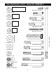
3. Tap a 60mm Square Inner Cap (28) into the top of each of the Front Uprights (7). 3 28 8 Attach one of the Front Uprights (7) and two Rack Joint Plates (6) to the Left Base (3) using four M10 x 78mm Bolts (31) and four M10 Nylon Locknuts (29). Make sure the Front Upright is oriented so that the holes on the bottom of the Front Upright and the holes in the Joint Plates line up. If they do not line up, turn the Front Upright upside-down. Do not tighten the Nylon Locknuts yet.
6. Press a 60mm Square Inner Cap (28) into the Left Frame (12). Attach the Left Frame to the left Uprights (7, 8) using four M10 x 78mm Bolts (31) and four M10 Nylon Locknuts (29). Do not tighten the Nylon Locknuts yet. 6 11 29 10 29 Assemble the Right Frame (10) on the right Uprights (7, 8) in the same manner. 31 Attach the Center Frame (11) to the Left Frame (12) and the Right Frame (10) using four M10 x 78mm Bolts (31) and four M10 Nylon Locknuts (29). Tighten all Nylon Locknuts used in steps 1–6.
10. Locate the High Cable (84), which is slightly longer than the Low Cable (not shown), and notice that there is a ball on one end of the Cable and a metal sleeve on the other end. 10 Route the metal-sleeve end of the High Cable (84) up under the lat bar rest on the Weight Guide Frame (14), down through the indicated hole, back up through the next hole, and then down between the Weight Guides (9) as shown. 14 9 Lat Bar Rest 84 11.
14. Pull the High Cable (84) down in the indicated location, so there is no slack at the ends of the Cable. 14 Locate the Low Cable (25), which has two balls on one end. Insert the metal-sleeve end of the Cable into the indicated hole in the Weight Guide Base (4). Attach the Cable using an M10 x 72mm Bolt (34), two M10 Washers (37), two 28mm Spacers (40), and a M10 Nylon Locknut (29). 84 Route the ball-end of the Low Cable (25) through the bracket on the Center Base (2).
17. Press a 51mm x 76mm Outer Cap (56) onto each end of the Stabilizer (58). 17 29 Attach the Stabilizer (58) to the Bench Frame (52) with two M10 x 58mm Carriage Bolts (57) and two M10 Nylon Locknuts (29). Attach the Stabilizer so that the warning decal is in the position shown. 56 52 Note: Do not tighten the Nylon Locknuts yet. Decal 58 57 18. Press a 50mm Square Outer Cap (65) onto each end of the Bench Base (53).
21. Lubricate a M10 x 192mm Bolt (66). Attach the Backrest Tubes (71) to the welded tube on the Bench Frame (52) with the Bolt, two M10 Washers (37), and a M10 Nylon Locknut (29). Note: Do not over tighten the Nylon Locknut; the Backrest Tubes must pivot easily. 21 Lubricate 37 66 71 Welded Tube 37 29 52 22. Attach the Backrest (60) to the Backrest Tubes (71) with four M6 x 52mm Screws (51) and four M6 Washers (74). 22 60 71 74 23. See the inset drawing.
25. Attach the Adjustable Bench Leg (49) to the Bench Leg (48) with the Small Adjustment Knob (81). 25 26 49 Insert a 45mm Square Inner Cap (26) into the top of the Adjustable Bench Leg (49). 81 48 26. Insert three 45mm Square Inner Caps (26) into the ends of the Leg Lever (62). Insert a 25mm Round Inner Cap (83) into the weight tube on the Leg Lever. Press a 25mm Angled Outer Cap (82) onto the other end of the weight tube.
Adjusting the Weight Rack This section explains how the weight rack and bench can be adjusted. See the Exercise Guidelines on page 17 for information about how to get the most benefit from your exercise program. See the included exercise poster for information about how to perform a variety of exercises. Inspect and tighten all parts each time you use the weight rack. Replace any worn parts immediately. The weight rack can be cleaned with a damp cloth and a mild, non-abrasive detergent. Do not use solvents.
ADJUSTING THE PAD TUBES For some exercises, it may be necessary to move the Pad Tube (61) in the Adjustable Bench Leg (49). To do this, remove a Foam Pad (69) from one side of the Pad Tube. Slide the Pad Tube out of the Adjustable Bench Leg. Reinsert the Pad Tube into the lower welded tube on the Adjustable Bench Leg. Replace the Foam Pad on the Pad Tube.
ATTACHING WEIGHTS TO THE WEIGHT CARRIAGE To use the high or low pulley station, slide the desired amount of weight onto the weight tubes on the Weight Carriage (15). Secure the weights with Weight Clips (43). Weight Tube Weight Tube WARNING: Do not place more than 150 pounds on the Weight Carriage (15). Always place the same amount of weight on each side of the Weight Carriage, and secure the weights on the Weight Carriage with the Weight Clips (43).
Exercise Guidelines THE FOUR BASIC TYPES OF WORKOUTS PERSONALIZING YOUR EXERCISE PROGRAM Muscle Building The only way to increase the size and strength of your muscles is to push them close to their maximum capacity. When you progressively increase the intensity of your exercise, your muscles will continually adapt and grow.
Make sure to rest for a short period of time after each set. The ideal resting periods are: • Rest for three minutes after each set for a muscle building workout. • Rest for one minute after each set for a toning workout. • Rest for 30 seconds after each set for a weight loss workout. Plan to spend the first couple of weeks familiarizing yourself with the equipment and learning the proper form for each exercise. each stretch gradually and go only as far as you can without strain.
EXERCISE MONDAY WEIGHT SETS REPS WEIGHT SETS REPS WEIGHT SETS REPS Date: / / AEROBIC EXERCISE TUESDAY Date: / / WEDNESDAY EXERCISE Date: / / THURSDAY AEROBIC EXERCISE Date: / / EXERCISE FRIDAY Date: / / Make photocopies of this page for scheduling and recording your workouts.
Part List—Model No. IMBE39401 Key No. Qty.
65 69 75 37 75 34 81 34 70 54 65 37 37 48 37 63 49 61 37 66 26 53 29 29 70 77 63 69 59 52 29 37 71 68 56 78 50 74 75 34 80 51 64 29 50 74 55 72 60 76 58 67 57 68 29 79 51 74 72 29 29 72 6 43 56 41 83 73 26 70 21 21 61 37 29 41 31 28 21 43 26 22 20 69 22 19 13 31 31 21 21 69 70 10 82 62 29 69 26 6 31 61 21 21 22 19 11 21 31 70 69 22 20 21 21 29 12 29 27 6 29 29 29 29 7 28 24 17 44 47
Ordering Replacement Parts To order replacement parts, simply call our Customer Service Department toll-free at 1-800-999-3756, Monday through Friday, 6 a.m. until 6 p.m. Mountain Time (excluding holidays). To help us assist you, please be prepared to give the following information when calling: • The MODEL NUMBER of the product (IMBE39401) • The NAME of the product (IMAGE® 5.