Model No. IMBE53910 Serial No. Write the serial number in the space above for reference. USER’S MANUAL Serial Number Decal QUESTIONS? As a manufacturer, we are committed to providing complete customer satisfaction. If you have questions, or if there are missing parts, we will guarantee complete satisfaction through direct assistance from our factory. TO AVOID DELAYS, PLEASE CALL DIRECT TO OUR TOLLFREE CUSTOMER HOT LINE.
TABLE OF CONTENTS WARNING DECAL PLACEMENT . . . . . . . . . . . . . . . . . . . . . . . . . . . . . . . . . . . . . . . . . . . . . . . . . . . . . . . . . . 2 IMPORTANT PRECAUTIONS . . . . . . . . . . . . . . . . . . . . . . . . . . . . . . . . . . . . . . . . . . . . . . . . . . . . . . . . . . . . . 3 BEFORE YOU BEGIN . . . . . . . . . . . . . . . . . . . . . . . . . . . . . . . . . . . . . . . . . . . . . . . . . . . . . . . . . . . . . . . . . . . 4 PART IDENTIFICATION CHART . . . . . . . . . . . . . .
IMPORTANT PRECAUTIONS WARNING: To reduce the risk of serious injury, read the following important precautions before using the weight bench. 1. Read all instructions in this manual before using the weight bench. Use the weight bench only as described in this manual. 10. The weight bench is designed to support a maximum of 560 pounds, including the user and weights. The weight rack is designed to support a maximum of 300 pounds, including the barbell and weights.
BEFORE YOU BEGIN Thank you for selecting the versatile IMAGE® 5.2 weight bench. The IMAGE® 5.2 is designed to help you develop every major muscle group of the body. Whether your goal is a shapely figure, dramatic increase in muscle size and strength, or a healthier cardiovascular system, the IMAGE® 5.2 will help you achieve the specific results you want. toll-free at 1-800-999-3756, Monday through Friday, 6 a.m. until 6 p.m. Mountain Time (excluding holidays).
PART IDENTIFICATION CHART This chart is provided to help you identify the small parts used in assembly. The number in parentheses below each part refers to the key number of the part from the PART LIST in the center of this manual. Important: Some parts may have been pre-assembled for shipping purposes. If you cannot find a part in the parts bags, check to see if it has been pre-assembled.
ASSEMBLY • As you assemble the weight bench, make sure all parts are oriented as shown in the drawings. Make Things Easier for Yourself Everything in this manual is designed to ensure that the weight bench can be assembled successfully by anyone. However, it is important to realize that the versatile weight bench has many parts and that the assembly process will take time. Most people find that by setting aside plenty of time, assembly will go smoothly.
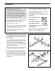
3. Attach an Upright (1) to each Base (7) using two Joint Plates (12), four M10 x 80mm Bolts (41), and four M10 Nylon Locknuts (11). Make sure the Uprights are oriented exactly as shown. Do not tighten the Nylon Locknuts yet. 3 1 41 7 1 12 7 12 11 12 12 41 4. Insert a Weight Guide (18) into the indicated hole in each Base (7). Attach the Weight Guides to the Bases using two M10 x 75mm Bolts (39), four M10 Small Washers (6), and two M10 Nylon Locknuts (11). Do not tighten the Nylon Locknuts yet.
7. Press a 38mm Bushing (29) into each side of the Left Weight Glider (32). Slide the Left Weight Glider onto the indicated end of the Barbell (35) and secure it to the Barbell using an M8 x 20mm Screw (50). Do not tighten the Screw yet. Make sure the Left Weight Glider is oriented exactly as shown. 7 35 29 32 50 29 8. Press a 50mm Bushing (47) into the indicated end of a Weight Adapter (33).
11. Press two Carriage Bushings (27) into the ends of the Weight Carriage (22). Press two 50mm Round Inner Caps (25) into the ends of the weight tube on the Weight Carriage. 11 2 Angled End 25 27 Insert an M10 x 20mm Bolt (26) into the bracket on the Weight Carriage (22). Weight Tube Slide the Weight Carriage (22) onto the Rear Upright (2) as shown. Make sure that the Weight Carriage and the Rear Upright are oriented as shown. 27 22 25 12.
15. Route the High Cable (13) around another Pulley (5) and through the indicated slot in the Pulley Bar (53) as shown. Attach the Pulley inside the slot using an M10 x 65mm Bolt (56), two M10 Large Washers (58), two Pulley Spacers (15), and an M10 Nylon Locknut (11). Do not overtighten the Nylon Locknut; the Pulley must be able to turn freely. 15 15 5 11 15 13 58 53 56 58 16.
19. Wrap the ball end of the Low Cable (8) around a Pulley (5). Attach the Pulley to the bracket on the Base Crossbar (20) with an M10 x 45mm Bolt (40) and an M10 Nylon Locknut (11). Do not overtighten the Nylon Locknut; the Pulley must be able to turn freely. Be sure the ball is on the indicated side of the bracket. 19 8 5 Ball 11 Bracket 40 20 20. Route the Low Cable (8) around a Pulley (5) as shown.
23. Press a 50mm Square Outer Cap (73) onto each end of the Bench Base (62). 23 Welded Nut 59 Attach the Bench Base Joint Plate (72) to the Bench Base (62) with two M10 x 70mm Bolts (91), two M10 Large Washers (58), and two M10 Nylon Locknuts (11). 58 91 62 Attach the Bench Leg (59) to the Bench Base Joint Plate (72) with two M10 x 70mm Bolts (91), two M10 Large Washers (58), and two M10 Nylon Locknuts (11). Be sure the welded nut is in the position shown.
27. Attach the Backrest (68) to the Backrest Tubes (78) with four M6 x 55mm Screws (90) and four M6 Washers (80). 27 68 78 80 90 28. Press the 20mm x 50mm Inner Cap (82) into the open end of the Seat Mounting Bracket (74). 28 30 84 Lubricate an M8 x 70mm Bolt (30). Attach the Seat Adjustment Bracket (84) to the indicated side of the Seat Mounting Bracket (74) with the Bolt and an M8 Nylon Locknut (54). Note: Do not overtighten the Nylon Locknut; the Seat Adjustment Bracket must pivot easily.
31. Attach the Adjustable Bench Leg (60) to the Bench Leg (59) with the Adjustment Knob (85). 31 88 60 Insert a 45mm Square Inner Cap (88) into the top of the Adjustable Bench Leg (60). 85 59 32. Insert three 45mm Square Inner Caps (88) into the ends of the Leg Lever (70). Insert a 25mm Round Inner Cap (87) into the weight tube on the Leg Lever. Press a 25mm Angled Outer Cap (86) onto the other end of the weight tube.
ADJUSTMENTS The weight bench is designed to be used with your own weight set (not included). The steps below explain how the weight bench can be adjusted. See EXERCISE GUIDELINES on page 18 for important exercise information and refer to the accompanying exercise guide to see the correct form for each exercise. Make sure all parts are properly tightened each time you use the weight bench. Replace any worn parts immediately.
ATTACHING WEIGHTS TO THE BARBELL OR THE WEIGHT CARRIAGE Weights To use the Barbell (35), slide the desired amount of weight (not included) onto each end of the Barbell. Secure the weights with Weight Clips (51). 35 51 Weights can be attached to the weight tube on the Weight Carriage (22) in the same manner. WARNING: Do not place more than 300 pounds on the Barbell (35), or more than 150 pounds on the Weight Carriage (22).
ADJUSTING THE PAD TUBES For some exercises, it may be necessary to move the Pad Tube (69) in the Adjustable Bench Leg (60). To do this, remove a Foam Pad (76) from one side of the Pad Tube. Slide the Pad Tube out of the Adjustable Bench Leg. Reinsert the Pad Tube into the lower welded tube on the Adjustable Bench Leg. Replace the Foam Pad on the Pad Tube.
EXERCISE GUIDELINES THE FOUR BASIC TYPES OF WORKOUTS PERSONALIZING YOUR EXERCISE PROGRAM Muscle Building To increase the size and strength of your muscles, push them close to their maximum capacity. Your muscles will continually adapt and grow as you progressively increase the intensity of your exercise. You can adjust the intensity level of an individual exercise in two ways: • by changing the amount of weight used • by changing the number of repetitions or sets performed.
Rest for a short period of time after each set. The ideal resting periods are: • Rest for three minutes after each set for a muscle building workout. • Rest for one minute after each set for a toning workout. • Rest for 30 seconds after each set for a weight loss workout. Plan to spend the first couple of weeks familiarizing yourself with the equipment and learning the proper form for each exercise. slowly as you stretch and do not bounce.
ORDERING REPLACEMENT PARTS To order replacement parts, simply call our Customer Service Department toll-free at 1-800-999-3756, Monday through Friday, 6 a.m. until 6 p.m. Mountain Time (excluding holidays). To help us assist you, please be prepared to give the following information when calling: • The MODEL NUMBER of the product (IMBE53910) • The NAME of the product (IMAGE® 5.
81 REMOVE THIS PART LIST/EXPLODED DRAWING FROM THE MANUAL
PART LIST—Model No. IMBE53910 Key No. Qty.
73 85 76 91 58 91 91 91 77 58 69 73 58 58 59 71 60 46 42 62 72 17 11 11 71 76 46 76 77 77 61 80 41 67 77 82 88 30 84 11 89 64 63 87 52 88 81 16 76 65 89 88 11 66 54 74 17 69 92 58 75 88 86 70 11 79 76 80 90 69 44 43 68 65 47 77 76 33 83 51 49 35 23 77 43 49 29 11 58 78 45 49 48 11 37 50 79 29 31 90 80 79 51 45 55 39 41 18 41 34 6 41 41 12 6 11 48 49 24 36 41 1 29 11 12 12 55 12 9 4