
Operation Manual

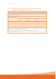


Table Of Contents
- 1. Quick Start
- 2. Introduction
- 3. Getting Started
- 3.1. Installation
- 3.2. Injector Features
- 3.3. Symbols
- 3.3.1. Symbols used in this manual
- 3.3.2. Symbols used on labelling
- 3.3.3. Handswitch and Footswitch
- 3.3.4. Icons and Buttons used on the Injector Touch Screen Graphical Interface
- 3.3.5. Injector Buttons
- 3.3.6. Remote Control Symbols and Buttons
- 3.3.7. Injector Visual Indicators
- 3.3.8. Icons and Buttons used on the RCU Touch Screen Graphical Interface
- 4. Clinical Information
- 5. Operation Description
- 5.1. Turning the System On for the First Time
- 5.2. Syringe, Quick Fill Tube, Fill Spike, and Connector Tubes
- 5.3. Filling a Syringe Using a Quick Fill Tube (QFT) or Fill Spike on the Injector
- 5.4. [Optional] Off-line Filling
- 5.5. Connector Tube Installation
- 5.6. Dismounting a Syringe
- 5.7. Performing an injection
- 5.8. Programming
- 5.9. Options Menu
- 5.10. [RCU models] Operation Description with Remote Control Unit
- 5.10.1. RCU Features–
- 5.10.2. The Injector and the RCU
- 5.10.3. Turning the System On / Off
- 5.10.4. Injector Controller Application
- 5.10.5. Filling State
- 5.10.6. Routine Protocol
- 5.10.7. Arming
- 5.10.8. Check for Air
- 5.10.9. Starting the Injection
- 5.10.10. Injection in Progress
- 5.10.11. Injection Control Buttons
- 5.10.12. Injection Review
- 5.10.13. Protocol Edit
- 5.10.14. Edit Lock
- 5.10.15. Parameter Value Edit
- 5.10.16. Injecting remaining volume
- 5.10.17. Edit Phase Type
- 5.10.18. Open Protocol
- 5.10.19. Protocol Save
- 5.10.20. Common Injecting Alarms / Warnings
- 5.10.21. RCU Manager
- 5.10.22. RCU Setup
- 5.10.23. History Viewer
- 5.10.24. Protocol Manager
- 5.10.25. eGFR (glomerular filtration rate) Calculator
- 5.11. [Optional] DC200 Scanner Interface
- 5.12. [Optional] Protocol Assistance Tool (PAT)
- 6. Cleaning and Maintenance
- 7. Trouble-shooting
- 8. Specifications
- 8.1. Dimensions
- 8.2. Mechanical
- 8.3. Functional
- 8.4. Controls
- 8.5. Environmental
- 8.6. Electrical
- 8.7. Connectors
- 8.8. IEC 60601-1 Classifications
- 8.9. Ground Continuity
- 8.10. RoHS Statement
- 8.11. IEC60601-1-2:2014 (4th Ed) Compliance
- 8.12. Models
- 8.13. Accessories
- 8.14. Manufacturer’s Software License Information
- 8.15. FCC Statement
- 9. Index

MEDRAD
®
Salient Operation Manual 91
8.11.3. Recommended separation distances from portable and mobile RF
communications equipment and the injector
Recommended separation distances from portable and mobile RF communications equipment and the injector
The injector is intended for use in an electromagnetic environment in which radiated RF disturbances are controlled. The customer
or the user of the injector can help prevent electromagnetic interference by maintaining a minimum distance between portable and
mobile RF communications equipment (transmitters) and the injector as recommended below, according to the maximum output
power of the communications equipment.
Rated maximum output
power of transmitter
W
Separation distance according to frequency of transmitter
m
150 kHz to 80 MHz
d = 1.2√P
80 MHz to 800 MHz
d = 1.2√P
800 MHz to 2.7 GHz
d = 2.3√P
0.01 0.1 0.1 0.2
0.1 0.4 0.4 0.7
1 1.3 1.3 2.3
10 3.8 3.8 7.3
100 12.0 12.0 23.0
For transmitters rated at a maximum output power not listed above, the recommended separation distance d in metres (m) can be
estimated using the equation applicable to the frequency of the transmitter, where P is the maximum output power rating of the
transmitter in watts (W) according to the transmitter manufacturer.
NOTE 1: At 80 MHz and 800 MHz, the separation distance for the higher frequency range applies.
NOTE 2: These guidelines may not apply in all situations. Electromagnetic propagation is affected by absorption and reflection
from structures, objects and people.