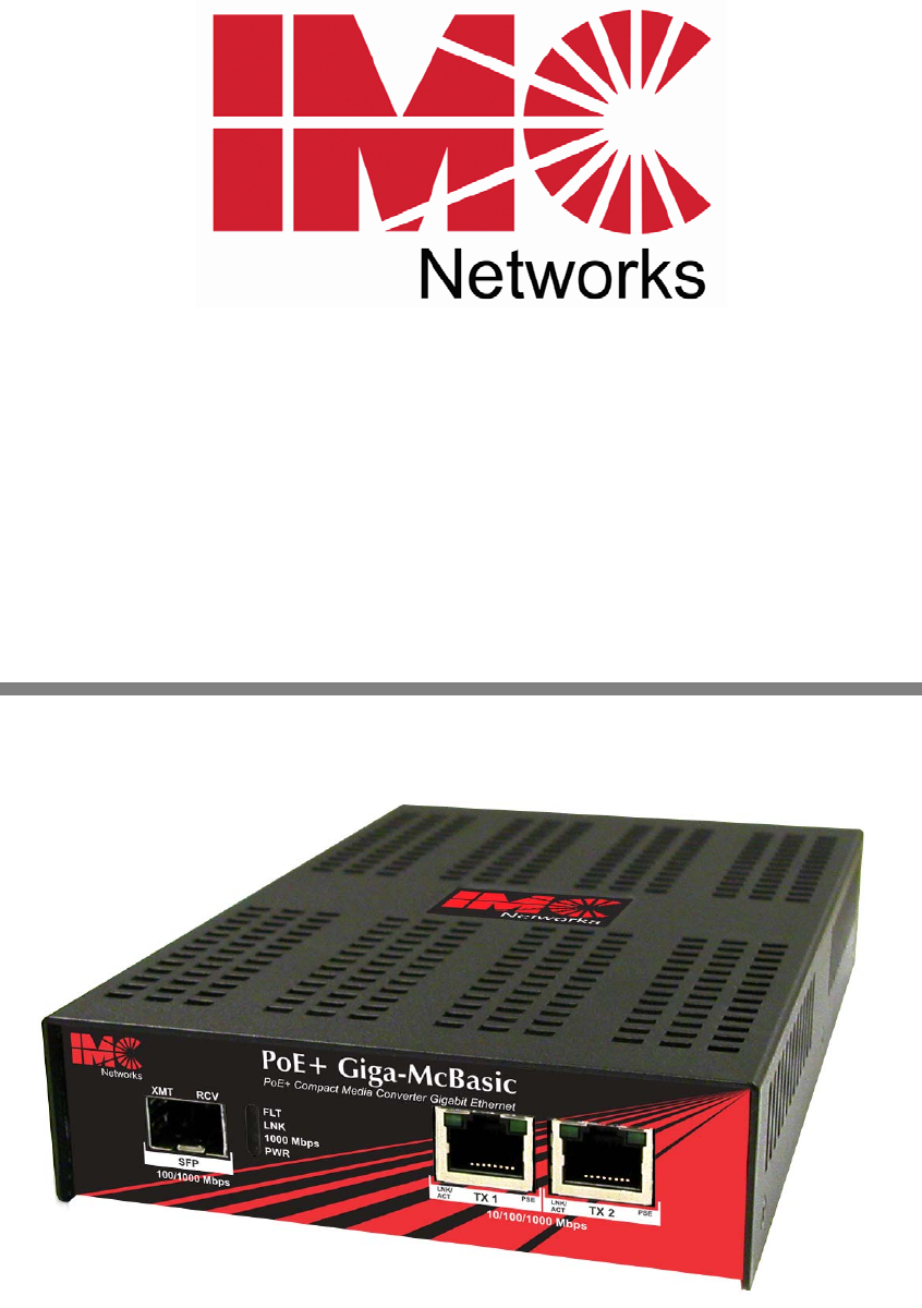
PoE Giga-McBasic and PoE+ Giga-McBasic Operation Manual Above illustration is representative; several models are available.
FCC Radio Frequency Interference Statement This equipment has been tested and found to comply with the limits for a Class B computing device, pursuant to Part 15 of the FCC Rules. These limits are designed to provide reasonable protection against harmful interference when the equipment is operated in a commercial environment.
Table of Contents FCC Radio Frequency Interference Statement ....................................................ii Warranty............................................................................................................ii About the PoE Giga-McBasic..............................................................................1 Installation .........................................................................................................2 DIP Switch Configuration SFP and 1x9 ..............
About the PoE Giga-McBasic The PoE Giga-McBasic is a solution for private network applications that require power over Ethernet for installations inside buildings where PoE is required to power an Ethernet device. The standalone unit offers a model with one SFP or fixed fiber transceiver, 1x9, uplink for the network connection, one PSE 10/100/1000Base-T copper port that provides Power-over-Ethernet (PoE) (IEEE802.3af), and one 10/100/ 1000Mbps copper port, to connect a non-PoE unit to the same fiber uplink.
Installation PoE Giga-McBasic installs virtually anywhere: as a standalone, table-top device, with rackmount ears,or using a Wallmount bracket. The rackmount ears and wallmount bracket are optional accessories available through IMC Networks distributors. Installation Tip Several models of the PoE Giga-McBasic support single-strand fiber for operation. Since singlestrand fiber products use optics that transmit and receive on two different wavelengths, singlestrand fiber products must be deployed in pairs.
NOTE Under no conditions will the LoSPd DSW impact any copper SFPs. Some 1000Mbps SFPs may not function properly when forced to 100Mbps. PoE Reset DSW When set to ON, it will force the PSE output power on the copper port OFF when the LINK state is lost on the SFP line (copper or fiber SFP). By default, the DSW is set to OFF.
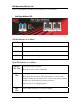
LED Operation SFP and 1x9 The PoE Giga-McBasic includes LEDs for three ports, as shown below: PoE Giga-McBasic SFP SFP LED Functions are as follows: FLT Glows red when a fault has been detected on the unit LNK Glows green with a valid link 1000 Mbps PWR Glows green when SFP is running at 1000Mbps Glows green when unit is powered RJ-45 LED Functions are as follows: LNK/ACT (TX1, TX2) PSE (TX2) Glows green with a valid link Blinks green when activity is detected Glows green when port is supplying PoE
PoE Giga-McBasic 1x9 1x9 LED Functions are as follows: FLT Glows red when a fault has been detected on the unit LNK Glows green with a valid link 1000 Mbps PWR Glows green when is running at 1000Mbps Glows green when unit is powered RJ-45 LED Functions are as follows: LNK/ACT (TX1.
Troubleshooting • PWR LED glows green when the unit is powered. If this LED is not lit, contact IMC Networks Technical Support. • If the PSE LED flashes twice at power-up, it may indicate an over current condition. The PSE LED should maintain solid green, to indicate consistent power. Check the PD device and its requirements. The following table lists the pin configuration for the RJ-48 connector.
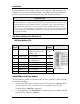
Specifications for the PoE Giga-McBasic Multi-mode 1300nm Dual Fiber Single-mode 1310nm 1550nm Dual Fiber Single-mode 1310nm 1490nm Single-Strand Fiber Single-mode 1310nm 1550nm Single-Strand Fiber Copper 10/100/1000Mbps Ethernet Connections 10/100/1000 BaseT Auto Negotiation AutoCross Flow Control 10240 MTU Full Line-Rate Forwarding Input Specifications 100 to 240 ±10% VAC input, 50/60 Hz, 0.5A to 0.
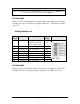
IMC Networks Products SFPs PoE Giga-McBasic Length of Warranty 1 year 6 year NOTE Please refer to the Warranty Section at the beginning of this manual for the full terms of the warranty.
About the PoE+ Giga-McBasic The PoE+ Giga-McBasic is a solution for private network applications that require power over Ethernet for locations inside buildings where PoE is required to power an Ethernet device. The standalone unit offers a model with one SFP or fixed fiber transceiver, 1x9, uplink for the network connection, two PSE 10/100/1000Base-T copper ports that provide Power-over-Ethernet (PoE) (IEEE802.3af) to connect a nonPoE unit to the same fiber uplink.
Installation PoE+ Giga-McBasic installs virtually anywhere: as a standalone, table-top device, with rackmount ears or using a Wallmount bracket. The rackmount ears and wallmount bracket are optional accessories available through IMC Networks distributors. Installation Tip Several models of the PoE+ Giga-McBasic support single-strand fiber for operation.
• Setting the LoSPd DSW to ON will force the SFP to operate at 100Mbps. When set in the default of OFF, the SFP will run at its maximum rate of the SFP installed. (100 or 1000 Mbps supported) If a dual speed fiber SFP 100/1000Mbps is installed, setting the LoSpd to ON will force the SFP to operate at 100Mbps • NOTE Under no conditions will the LoSPd DSW impact any copper SFPs. Some 1000Mbps SFPs may not function properly when forced to 100Mbps.
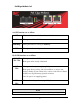
LED Operation SFP and 1x9 The PoE+ Giga-McBasic includes LEDs for three ports, as shown below: PoE+ Giga-McBasic SFP SFP LED Functions are as follows: FLT Glows red when a fault has been detected on the unit LNK Glows green with a valid link 1000 Mbps PWR Glows green when SFP is running at 1000Mbps Glows green when unit is powered RJ-45 LED Functions are as follows: LNK/ACT (TX1, TX2) Glows green with a valid link PSE (TX1, TX2) Glows green when port is supplying PoE power Blinks green when activ
PoE+ Giga-McBasic 1x9 1x9 LED Functions are as follows: FLT Glows red when a fault has been detected on the unit LNK Glows green with a valid link 1000 Mbps PWR Glows green to indicate is running at 1000Mbps Glows green when unit is powered RJ-45 LED Functions are as follows: LNK/ACT (TX1, TX2) Glows green with a valid link PSE (TX1, TX2) Glows green when port is supplying PoE power Blinks green when activity is detected Blinks green during training and fault conditions: a series of two flashes
Troubleshooting If the PoE+ Giga-McBasic is not responding to the power provided to it, the following conditions may be responsible: • There may be an over current condition; this is indicated on the PSE LED by a series of two flashes. • There may be an invalid low or high discovery signature resistance; this is indicated on the PSE LED by a series of five flashes. • If the PoE injector has power that can be verified, but the PSE LED is off, then contact IMC Networks technical support.
Specifications for the PoE+ Giga-McBasic Multi-mode 1300nm Dual Fiber Single-mode 1310nm 1550nm Dual Fiber Single-mode 1310nm 1490nm Single-Strand Fiber Single-mode 1310nm 1550nm Single-Strand Fiber Copper 10/100/1000Mbps Ethernet Connections 10/100/1000 BaseT Auto Negotiation AutoCross Flow Control 10240 MTU Full Line-Rate Forwarding Input Specifications Input Specifications 100 to 240 ± 10% VAC input, 50/60 Hz, 1.6A to 0.
IMC Networks Products SFPs PoE+ Giga-McBasic Length of Warranty 1 year 6 year NOTE Please refer to the Warranty Section at the beginning of this manual for the full terms of the warranty. PoE Precautions (For Inside-a-Building Installation ONLY) The PoE Giga-McBasic and PoE+ Giga-McBasic are for inside-a-building installation only. Both devices cannot be installed outside-a-building environment, as they cannot meet the PoE requirements, per the PoE standard.
IMC Networks Technical Support Tel: (949) 465-3000 or (800) 624-1070 (in the U.S. and Canada); +32-16-550880 (Europe) Fax: (949) 465-3020 E-Mail: techsupport@imcnetworks.com Web: www.imcnetworks.
Fiber Optic Cleaning Guidelines Fiber Optic transmitters and receivers are extremely susceptible to contamination by particles of dirt or dust, which can obstruct the optic path and cause performance degradation. Good system performance requires clean optics and connector ferrules. 1. 2. 3. 4. Use fiber patch cords (or connectors, if you terminate your own fiber) only from a reputable supplier; low-quality components can cause many hard-to-diagnose problems in an installation.
Electrostatic Discharge Precautions Electrostatic discharge (ESD) can cause damage to any product, add-in modules or stand alone units, containing electronic components. Always observe the following precautions when installing or handling these kinds of products 1. Do not remove unit from its protective packaging until ready to install. 2. Wear an ESD wrist grounding strap before handling any module or component.
Safety Certifications UL/CUL: Listed to Safety of Information Technology Equipment, including Electrical Business Equipment. CE: The products described herein comply with the Council Directive on Electromagnetic Compatibility (2004/108/EC) and the Council Directive on Electrical Equipment Designed for use within Certain Voltage Limits (2006/95/EC). Certified to Safety of Information Technology Equipment, Including Electrical Business Equipment. For further details, contact IMC Networks.
19772 Pauling • Foothill Ranch, CA 92610-2611 USA TEL: (949) 465-3000 • FAX: (949) 465-3020 www.imcnetworks.com © 2012 IMC Networks. All rights reserved. The information in this document is subject to change without notice. IMC Networks assumes no responsibility for any errors that may appear in this document. PoE Giga-McBasic and PoE+ Giga-McBasic- is a trademark of IMC Networks. Other brands or product names may be trademarks and are the property of their respective companies.