McBasic TP/FO & TP/BNC Operation Manual
FCC Radio Frequency Interference Statement This equipment has been tested and found to comply with the limits for a Class B computing device, pursuant to Part 15 of the FCC Rules. These limits are designed to provide reasonable protection against harmful interference when the equipment is operated in a commercial environment.
Table of Contents FCC Radio Frequency Interference Statement ....................................................ii Warranty............................................................................................................ii About the McBasic .............................................................................................1 Installing the McBasic.........................................................................................1 Configuring McBasic ...............................
Notes iv
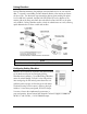
About the McBasic The McBasic series consists of low-cost, IEEE 802.3 single-conversion, 1U high, standalone media converters. The McBasic TP/FO converts 10Base-T twisted pair to 10Base-FL multi-mode or single-mode fiber and includes one RJ-45 connector and one pair of ST or SC connectors. McBasic TP/BNC converts 10Base-T twisted pair to 10Base-2 thin coax and includes one RJ-45 connector and one BNC connector. Each McBasic includes diagnostic LEDs and an internal 100/240 VAC power supply.
BNC Port Termination McBasic TP/BNC features a 2-position switch next to the BNC connector that allows a thin coaxial segment to be terminated at the port without an additional ‘T’ connector and terminator. If McBasic TP/BNC is attached to a mid-point of a thin Ethernet segment, attach a ‘T’ connector to the BNC port. Termination must be OFF (disabled). Termination is disabled when the switch is in the left position.
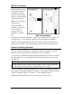
About Link Integrity During normal operation, link integrity pulses are transmitted by all point-to-point Ethernet devices. When an IMC Networks media converter receives valid link pulses, it knows that the device to which it is connected is up and sending pulses, and that the copper or fiber cable coming from that device is intact. The appropriate “LINK” LED is lit to indicate this.
Pulsing FiberAlert Pulsing FiberAlert minimizes the problems associated with the loss of one strand of fiber. If a strand is unavailable, the IMC Networks device at the receiver end notes the loss of link. The device will stop transmitting data and start sending link pulses. Until a valid link is received, the fiber link LED will be OFF on the device on the receiver side of the fiber strand with the fault while the fiber Link LED on the other unit will blink.
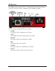
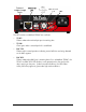
LED Operation Each McBasic features diagnostic LEDs. The following illustrations show the location of the LEDs, and other features, on McBasic TP/FO and McBasic TP/BNC. The LED functions for McBasic TP/FO are as follows: • TP LINK Glows green if link is established on the TX port. • TP ACT Glows amber when data is being passed on the TX port. • FA PULSE Glows green when Pulsing FiberAlert is enabled. • PWR Glows green when unit has power.
The LED functions for McBasic TP/BNC are as follows: • TP RCV Flickers amber when twisted pair port is receiving data. • TP LNK Glows green when a twisted pair link is established. • BNC COL Flickers red in normal operation indicating normal collisions are being detected on the BNC segment. • BNC RCV Flickers amber when BNC port is receiving data (On a -20 McBasic TP/BNC, the TP RCV and BNC RCV LEDs flicker at a rate proportional to the rate that the data is passing on the ports.
Installation Troubleshooting • During installation, first test your fiber and twisted pair connections with all troubleshooting features disabled. Then enable these features, if desired, just before final installation. This will reduce the interference from features upon testing. • To test McBasic TP/FO by itself, you must have an appropriate fiber patch cable. First, connect McBasic TP/FO to the twisted pair device with a twisted pair cable and establish valid link.
IMC Networks Technical Support Tel: (949) 465-3000 or (800) 624-1070 (in the U.S. and Canada); +32-16-550880 (Europe) Fax: (949) 465-3020 E-Mail: techsupport@imcnetworks.com Web: www.imcnetworks.com Specifications Power AC Input Load: 100/240V±10% ~ 50/60 Hz, 0.1/0.05A Operating Temperature: 32° to 104° F (0° to 40° C) Storage Temperature: -4° to 158° F (-20° to 70° C) Humidity: 5 to 90% (non-condensing); 0 to 10,000 ft. altitude Shipping weight: 1.3 lbs. (0.
Dimensions: McBasic TP/FO 1.68”H x 4.75”W x 4.95”D (4.3 cm x 12.1 cm x 12.6 cm) McBasic TP/BNC 1.68"H x 4.75"W x 4.53"D (4.3 cm x 12.1 cm x 11.
Fiber Optic Cleaning Guidelines Fiber Optic transmitters and receivers are extremely susceptible to contamination by particles of dirt or dust, which can obstruct the optic path and cause performance degradation. Good system performance requires clean optics and connector ferrules. 1. Use fiber patch cords (or connectors, if you terminate your own fiber) only from a reputable supplier; low-quality components can cause many hard-to-diagnose problems in an installation. 2.
Safety Certifications UL/CUL: Listed to Safety of Information Technology Equipment, including Electrical Business Equipment. CE: The products described herein comply with the Council Directive on Electromagnetic Compatibility (89/336/EEC) and the Council Directive on Electrical Equipment Designed for use within Certain Voltage Limits (73/23/EEC). Certified to Safety of Information Technology Equipment, Including Electrical Business Equipment. For further details, contact IMC Networks.
19772 Pauling • Foothill Ranch, CA 92610-2611 USA TEL: (949) 465-3000 • FAX: (949) 465-3020 www.imcnetworks.com © 2008 IMC Networks. All rights reserved. The information in this document is subject to change without notice. IMC Networks assumes no responsibility for any errors that may appear in this document. McBasic is a trademark of IMC Networks. Other brands or product names may be trademarks and are the property of their respective companies.