
Instruction manual


6 DMX Control
DMX (digital multiplex) makes it possible to dig-
itally control several DMX units via a common
control cable. For operation via a DMX light
controller (e. g. DMX-1440 from “img Stage
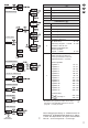
Line”) the spotlight is provided with 7 DMX
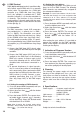
channels; however, it can also be controlled via
4 channels. The functions in the 4-channel
mode and the 7-channel mode with the corre-
sponding DMX values can be found in the table
on the right (fig. 2).
6.1 Connection
For DMX connection, 3-pole XLR connectors
are provided (pin 1 = ground, pin 2 = DMX
-
,
pin 3 = DMX+). For connection, use special
cables for DMX signal transmission (e. g. cables
of the CDMXN series from “img Stage Line”).
For cable lengths exceeding 150m, it is gener-
ally recommended to insert a DMX level match-
ing amplifier (e. g. SR-103DMX from “img Stage
Line”).
1) Connect the DMX input (XLR chassis plug)
of the spotlight to the DMX output of the light
controller.
2) Connect the DMX output (XLR jack) of the
spotlight to the DMX input of the following
DMX unit; connect its output again to the
input of the following unit etc. until all DMX-
controlled units have been connected in a
chain.
3) To prevent interference in signal transmis-
sion, in case of long cables or a multitude of
units connected in series, terminate the DMX
output of the last DMX unit in the chain with a
120Ω resistor (> 0.3 W): Connect a corre-
sponding terminating plug (e. g. DLT-123
from “img Stage Line”) to the DMX output
jack.
6.2 Setting the number of DMX channels
1) Press the button MENU repeatedly until you
reach the highest menu level.
2) Select the menu item with the button
UP or DOWN.
3) Press the button ENTER: The current chan-
nel mode ( 4 channels, 7 channels)
will be displayed. Select the desired mode
with the button UP or DOWN.
Note: After changing the channel mode during
operation, always return to the address set in the
menu ( …) to confirm the change.
6.3 Setting the start address
For controlling the spotlight, set a DMX start ad-
dress for its first DMX channel. The following
DMX channels are automatically assigned to
the subsequent addresses.
Example: In case of start address 5 in the 7-chan-
nel mode, the channels 2 to 7 are assigned to the
addresses 6 to 11. Thus, address 12 is the next
possible free start address for the following DMX-
controlled unit.
1) Press the button MENU repeatedly until you
reach the highest menu level.
2) Select the menu item with the button
UP or DOWN.
3) Press the button ENTER: The current ad-
dress (e. g. ) will be displayed. Set the
desired address with the button UP or
DOWN.
After setting the start address, it is possible to
operate the spotlight via the DMX controller.
When control signals are received, a dot starts
flashing on the display.
7 Indication of Firmware Version
1) Press the button MENU repeatedly until you
reach the highest menu level.
2) Select the menu item with the button UP
or DOWN.
3) Press the button ENTER: The current ver-
sion number of the firmware (operating sys-
tem of the spotlight) will be displayed.
8 Cleaning
For cleaning the power supply unit and the
housing of the spotlight only use a dry, soft
cloth; never use water or chemicals. For clean-
ing the lens, you may also use a glass cleaner.
Always make sure that no fluid gets inside the
unit.
9 Specifications
Power supply: . . . via power supply unit pro-
vided and connected
to 230V~ / 50Hz
Light source: . . . . RGBW LED, 10W
Beam angle: . . . . 7°
Dimensions: . . . . 100 × 122 × 128 mm
Weight: . . . . . . . . 660 g
Subject to technical modification.
10
GB