
User manual


6
English
Deutsch
Deutsch Seite
Français
Français Page
Italiano
Italiano Pagina
Español
Español Página
Nederlands
Nederlands Pagina
Polski
Polski Strona
English
English Page
Digital PA Amplifier
with 4 or 8 Channels
These instructions are intended for users
without any specific technical knowledge.
The speakers, however, should only be con-
nected by persons with the corresponding
technical knowledge. Please read these
instructions carefully prior to operating the
unit and keep them for later reference.
All operating elements and connections
described can be found on the fold-out
page3.
1 Operating Elements
andConnections
1 Button MUTE to mute the corresponding
channel
2 Indicator CLIP for each channel
lights up when the channel is overloaded
3 Volume control LEVEL for each channel
4 Switch POWER
5
Balanced inputs as XLR jacks for each
channel; in case of bridge mode, only
connect the odd-numbered input
6 Unbalanced inputs as RCA jacks for each
channel; in case of bridge mode, only
connect the odd-numbered input
7 Switch for the operating mode, one for
each channel pair
NORMAL = each channel operates sepa-
rately
BRIDGE = bridge mode
8 Speaker terminals
9 Support for the mains fuse
Only replace a blown fuse by one of the
same type!
10
Mains jack for connection to a socket
(230 V/ 50 Hz) via the supplied mains cable
2 Safety Notes
The unit corresponds to all relevant directives
of the EU and is therefore marked with .
WARNING The unit is supplied with haz-
ardous mains voltage. Leave
servicing to skilled personnel
only and do not insert anything
into the air vents! Inexpert
handling may result in electric
shock.
•
The unit is suitable for indoor use only. Pro
-
tect it against dripping water and splash
water, high air humidity, and heat (admis-
sible ambient temperature range 0 – 40 °C).
•
Do not place any vessels filled with liquid,
e. g. drinking glasses, on the unit.
•
The heat being generated in the unit must
be dissipated by air circulation; never cover
the air vents of the housing.
•
Do not set the unit into operation, and im-
mediately disconnect the mains plug from
the mains socket if
1. there is visible damage to the unit or to
the mains cable,
2.
a defect might have occurred after a drop
or similar accident,
3. malfunctions occur.
The unit must in any case be repaired by
skilled personnel.
•
Never pull the mains cable to disconnect
the mains plug from the mains socket,
always seize the plug.
•
For cleaning only use a dry, soft cloth, never
use chemicals or water.
•
No guarantee claims for the unit and no
liability for any resulting personal damage
or material damage will be accepted if the
unit is used for other purposes than orig-
inally intended, if it is not correctly con-
nected or operated, or if it is not repaired
in an expert way.
•
Important for U. K. Customers!
The wires in this mains lead are coloured
in accordance with the following code:
green / yellow = earth
blue = neutral
brown = live
As the colours of the wires in the mains
lead of this appliance may not correspond
with the coloured markings identifying the
terminals in your plug, proceed as follows:
1.
The wire which is coloured green and yel
-
low must be connected to the terminal in
the plug which is marked with the letter
E or by the earth symbol ⏚, or coloured
green or green and yellow.
2.
The wire which is coloured blue must
be connected to the terminal which is
marked with the letter N or coloured
black.
3. The wire which is coloured brown must
be connected to the terminal which is
marked with the letter L or coloured red.
Warning – This appliance must be earthed.
If the unit is to be put out of oper-
ation definitively, take it to a local
recycling plant for a disposal which
is not harmful to the environment.
3 Applications
This digital amplifier is ideally suited for
simultaneous PA application in several rooms.
For this purpose, model STA-450D is equipped
with four channels, model STA-850D with
eight channels. Each channel is able to deliver
an RMS power of 50 W.
For a higher output power, two channels
each can be bridged. Due to the bridge circuit,
an RMS power of 100 W can be delivered per
channel pair.
4 Setting up the Amplifier
The amplifier is designed for installation into
a rack (482 mm / 19”) but can also be used as
a tabletop unit. In order to ensure sufficient
cooling of the amplifier, air must always be
able to flow freely through all air vents.
4.1 Rack installation
For rack installation, the amplifier requires
2 RS (RS = rack space = 44.45 mm). To prevent
the rack from becoming top-heavy, insert the
amplifier into the lower section of the rack.
The front plate is not sufficient for fixing the
amplifier safely; additionally use lateral rails or
a bottom plate to secure the amplifier.
The hot air given off by the amplifier must
be dissipated from the rack; otherwise heat
will accumulate in the rack which may not
only damage the amplifier but also other units
in the rack. In case of insufficient heat dissi-
pation, install a ventilation unit into the rack.
5 Connecting the Amplifier
All connections must only be made or
changed with the unit switched off!
1)
Connect the signal sources (e. g. CD
player, preamplifier, mixer) to the jacks
INPUT (5, 6).
The XLR jacks (5) are designed for bal-
anced signals and, for rated power, require
an input signal of 550 mV as a minimum.
Connect signal sources with unbal-
anced signals to the RCA jacks (6). For
rated power, a signal of 1 V as a minimum
is required.
For channel pairs intended for bridge
mode (
☞
chapter 6.1), only connect the
odd-numbered input.
2)
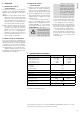
Connect the speakers to the terminals
OUTPUT (8). The table on page 3 shows
the required power rating (Pmin) of the
speakers.
For channels operating in normal
mode [switch (7) in position NORMAL],
connect the marked core of the speaker
cable to the red terminal and the other
core to the black terminal. In normal mode,
the highest output power will be reached
with 4 Ω speakers. Speakers with lower
impedance (Z) must not be connected; the
amplifier may be damaged. 8 Ω speakers
may be connected; in this case, the output
power will slightly decrease.
For channel pairs operating in bridge
mode [switch (7) in position BRIDGE],
connect the marked core of the speaker
cable to the left, red terminal of the chan-
nel pair and the other core to the right,
red terminal (see imprint BRIDGE at the
terminals). In bridge mode, the maximum
output power will be reached with an 8 Ω
speaker. Speakers with lower impedance
(Z) must not be connected; the amplifier
may be damaged. Speakers with higher
impedance may be connected; in this case,
the output power will slightly decrease.
3)
First connect the mains cable to the mains
jack (10) and then the mains plug of the
cable to a socket (230 V/ 50 Hz).