
User manual

ImmersionRC | EzOSD Manual
4
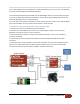
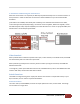
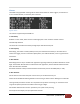
at all. A wiring diagram for this configuration is shown below. When the current sensor is not detected,
the lower line of the OSD will automatically disappear.
3) The telemetry downlink from the EzOSD uses the AUDR (Right channel of a stereo audio pair) signal.
In the case of using ImmersionRC A/V transmitters, which transmit high-bandwidth stereo audio, the
standard cabling will connect this signal correctly.
In the case that 3
rd
-Party video transmitters are used, possibly with mono-audio, ensure that the AUDR
signal from the OSD is correctly routed to the transmitter’s audio input pin.
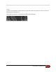
1. Installation using an ImmersionRC camera and transmitter
1. Connect the current sensor between the LiPo and the ESC
2. Hook the 4-pin cable between the current sensor and the OSD (it is keyed, can’t be inserted
backwards, and only fits into the correct connectors)
3. Remove the the 5-pin camera connector from the video transmitter, insert it into the Video-In
connector of the OSD
4. Connect the 5-pin cable, supplied with the OSD, and hook it between the OSD and the video
transmitter.
5. (optional) If this is a new installation, and the video transmitter has not yet been cabled for power,
take the 2-pin cable supplied with the OSD and hook it between the current sensor and the video
transmitter (this will just pass the battery voltage to the Video Transmitter).