250 Pro Instruction manual International edition Rev 1.
Table of Contents Table of Contents Living Manual Thank You! Getting Started, ARF Version The Anatomy of a Vortex Connectors and Switches Connector Part Numbers and Sources Arm Assembly Camera Mounting Plate Flight Camera GoPro Camera Mount Lost Model Alarm The On Screen Display (OSD) The Welcome Screen The Main Menu The LED Setup Menu The Flight Controller Menus The Video Tx Menu Flight Controller R/C Transmitter Control Modes Flight Modes Betaflight / Cleanflight / Baseflight / Multiwii / Open-Source Clea
Flight Controller Stick Commands Overview RotorSENSE Pro-Tuning R/C (Uplink) Receiver Selection CPPM SBus, or Spektrum Notes on Receiver Selection Receiver Auto-Detection Version 1: OSD Firmware prior to ???.??? Spektrum™ Radios FrSky Taranis Radio Futaba S-Bus Radios Version 2: OSD Firmware from ???.
Appendix A: EzUHF Configuration Appendix B: The Wizard - What else does it setup? Appendix C: Video Tx - Staying Legal ITU Region 2: Americas, Greenland, eastern Pacific Islands ITU Region 1: Europe, Africa, Middle East, Iraq, Soviet Union ITU Region 1: Europe, Africa, Middle East, Iraq, Soviet Union Appendix D: LED Board - Status report Looking after your Vortex Snow and Water The Sun Dirt Jealous Friends Specifications Spare parts and Upgrades Support Frequently Asked Questions Q.
Q. My vortex beeps continuously Q. My vortex is playing Crazy Train song Q. My vortex emits 2 long beeps followed by a short beep on startup (--·) Q. When I fly, all I see is the ground Q. My Vortex flips instead of taking off Q. I updated to the latest BetaFlight x.y.
Living Manual Note that this manual is a ‘living manual’. Instead of downloading a static PDF file, the manual is an online document which reflects edits, additions, and corrections as they happen. The Living Manual also allows readers to add their comments, which editors can use to refine the documentation. Confused by part of the manual? Wishing for a better explanation for part of the setup? Leave a note and the editors will listen.
WARNING Congratulations on your purchase of one of the hobby’s first ARF pure-bred racing quadcopters. A product designed by FPV Racers, for FPV Racers. Do not expect it to fly like a DJI Phantom™ . It does not have a return-to-home feature, no GPS, and it does not have stabilization features that will allow your girlfriend to fly it.
Getting Started, ARF Version The separate Getting Started guide should be used when setting up your Vortex 250 Pro for the first time. It includes sections on choosing an appropriate battery, and R/C receiver, and also the operation of the setup wizard.
The Anatomy of a Vortex Connectors and Switches 1) USB connector , used to configure the flight controller and upgrade the Vortex firmware. Note that to use the USB connector, a battery must be connected also. The Vortex cannot be powered through the USB connector. Please be careful not to put too much strain on this connector. It is a lightweight surface-mount part, and if the quad is dragged around by the USB cord it may not survive.
Note: To bind a Spektrum Rx using the rear button, the vortex must be placed in SPEKTRUM 1024/2048 mode, and not AUTO mode, using the Vortex Configurator on a PC or Mac. 3) Fusion FC/OSD button , used to enter firmware update mode in the case of a ‘bricked’ OSD. Note that this button is not required in normal use with the bootloader and firmware shipped with the 250 Pro. . See the Firmware Upgrades chapter for more details. 4) Socketed Video Tx Module Either a 350mW, or 25mW 5.
ejected from the side of the quad, into awaiting fingers… Be sure to reinstall the spring when re-assembling the Vortex, to avoid the Tx module from damage in a crash. 5) Flight Camera Video/Power Connector The flight camera video and power connector is a 3-pin Picoblade connector located behind the flight camera. The connector can be easily accessed without the need to disassemble the quad. Looking from the front of the quad, the pinout is as follows, left to right: 1. Video 2. Gnd 3.
The connector has the following pinout, starting from the front of the quad: 1. +5V 2. Gnd ~1A Maximum Current NOTE: Certain GoPro models will not power up without a battery installed, a little research may be required to identify which ones . 7) Receiver PPM Connector (CPPM Only) When using a classic PPM (a.k.a. CPPM) receiver, use the PPM connector, a 3-pin JST-PH connector with the following pinout, looking from right to left in the below image: 1. Gnd 2. +5V 3. PPM Power to the receiver 3.
8) Receiver Serial Connector When using receivers which emit a serial protocol (most of the receivers used in Drone Racing today), an alternative connector, located on the top of the Fusion Gen2 PCB is used. This connector contains both a +5V, and a +3.3V supply, to support most of the receivers on the market today. For longer-range flight, the latest EzUHF firmware allows the 4 channel Lite receiver to be connected using the S-Bus protocol.
9) XT-60 Battery Connector The pre-installed XT-60 connector is compatible with most batteries of the size and capacity in the class required by the Vortex. Note: Pay EXTREME attention to the polarity of batteries connected to this connector, especially those soldered ‘DIY’. A reverse-polarity connection, even for a fraction of a second will let out the ‘magic smoke’ and destroy most of the electronics in the Vortex.
Arm Assembly When changing the arm, a soldering iron is required, to remove the ESC + and - battery cables. Note: The choice of soldered connections here, instead of the much more convenient connector option may not seem ideal. Various connectors were tried, but one compact enough, robust enough, and capable of carrying > 20 Amps per motor was not found. A custom connector suitable for this application will be included in a future revision of the Vortex to simplify the in-field replacement of arms.
Camera Mounting Plate Flight Camera The Vortex flight camera is suspended from a dampened carbon fiber plate. This reduces the amount of Jello due to unbalanced (or slightly damaged) props. The camera mount itself allows a tilt of up to ~45 degrees, compensating for frame tilt due to high speed racing. NOTE: The camera pivot point is intentionally tiltable without tools. Because of this, it may move after the occasional ‘hard landing’, and should be checked before the next launch.
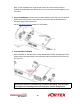
GoPro Camera Mount The Vortex 250 Pro ships with a GoPro camera ‘recliner’ kit, which may be optionally installed. This kit tilts the GoPro camera to an angle appropriate for high speed flight, while providing mounting points to securely fasten the camera to the quad. To install the recliner kit, the anti-vibe camera mounting plate must be removed following these simple steps: 1) Remove both side-plates from the quad.
The On Screen Display (OSD) The Welcome Screen Each time the Vortex is powered up, and before sticks are moved, the following welcome screen is displayed. This shows various pieces of status information, including the Flight Controller version number, and Flight Controller API version which is fairly important for OSD compatibility. Moving the pitch/roll stick (right stick for mode 2’ers) will dismiss the menu.
The Main Menu For Mode 2’ers, holding the throttle stick down and to the left will enter the main menu. Note that this stick position needs to be held for a few seconds before the menu appears. To navigate the menu, use the pitch/roll stick.
The OSD Setup Menu Various OSD setup parameters are available in this menu. The Landscape , defines the elements that are shown on the main screen in flight, including an EzOSD-type landscape (the default), a clutter-free landscape for hardcore racers, and a gaming mode which is currently in Beta form (documented later in this manual). The Pseudo lets you name your quad. This is useful when several Vortexes are being used in a race, and simplifies Video Tx channel assignments.
Alarms may be enabled and disabled in the Alarms Setup menu. It is highly recommended to start flying with all alarms enabled, and disable them if required after getting used to the quad.
The LED Setup Menu The RGB LEDs on the rear of the Vortex are fully programmable, with colors, and various patterns. For Parameter Mode = Intensity , the intensity of the LEDs will reflect the current throttle position. For Parameter Mode = Frequency the blink rate of the LEDs will reflect the current throttle position. For Parameter Mode = Gradient , the LEDs will shift from the foreground color, to the background color, based upon the current throttle position.
The Flight Controller Menus In-field tweaking of flight-controller menus is possible without a laptop and USB cable. All of the critical parameters, PIDs, Expos, Loop time, etc. are available. Note that the PID Setup menu is a two page menu, keep moving the caret down to access the second page.
Note that all of the Flight Controller parameters can be preset by loading one of the installed Pro-Tunes .
The Video Tx Menu The Video Tx menu shows, graphically, the 5.8GHz frequency band, from low (left) through high (right) frequency. 5 bands are supported, covering the standard ImmersionRC/FatShark frequency bands, plus all of the ‘Boscam’, Team Black Sheep bands, and also the new ImmersionRC ‘RaceBand’. Note the need for RaceBand in this hobby is immediately obvious after looking at this graph! NOTE: Channel 8 of the IRC/FS set cannot be received by 7 channel ImmersionRC or FatShark receivers.
Flight Controller R/C Transmitter Control Modes Mode 1 - Common in Europe Pitch Throttle Yaw Roll Mode 2 - Common in the USA Throttle Pitch Yaw Roll Mode 3 Pitch Throttle Roll Yaw Mode 4 Throttle Pitch Roll Yaw 28
Flight Modes Three flight modes are configured by the Vortex Wizard, and are mapped by default to channel 5 of the R/C Tx. These modes are as follows: Acro This mode is the preferred mode for the more advanced mini-quad pilot. In many ways it is the simplest mode, but also the hardest mode to learn. In Acro mode, the accelerometer part of the IMU is not used, only the Gyro. Because of this, the quad will not self-level, explaining the steep learning curve for this mode.
Betaflight / Cleanflight / Baseflight / Multiwii / Open‐Source The development of the Vortex would not have been possible without the effort of a large team of individuals who invested in the open source flight controller software that running on the Vortex. The variant of the open source flight controller firmware that we chose to power the Vortex is Betaflight, mainly due to it’s solid support of the OneShot ESC control protocol.
Flight Controller Stick Commands Enter Menu/Disarm Flight Controller: Mode 2: Mode 1: Throttle stick left, and down (normal flight controller disarm control) Yaw left, Throttle stick down Arm Flight Controller: Mode 2: Mode 1: Throttle stick right, and down Yaw right, Throttle stick down Reset vTx Channel: Mode 2: Mode 1: Throttle Down, Rudder Left + Elevator Up, Aileron Left Throttle Down, Rudder Left + Elevator Up, Aileron Left 31
ESCs - The 20A Vortex 250 ESC Overview The ESCs used in the Vortex are a full-custom design, which uses a potent 32-bit ARM processor. Their diminutive 9.4mm width allows them to be inserted into the carbon fiber arms of the Vortex 285, or into the plastic ESC covers of the 250, where they are well protected against the elements, and from physical damage from passing tree-branches.
Pro-Tuning During the development of the Vortex, a team of pro-quad pilots spent countless hours, tweaking the tuning (PIDs) of the flight controller, using various ‘PID Controllers’ supported by the Cleanflight firmware Each pilot fed back this data to the ImmersionRC team, and we incorporated it into the OSD firmware. Now, as a user, you can choose your favourite pilot, choice of props, battery, flight style, etc. and all flight controller settings are configured for you, based upon his pro-tune.
R/C (Uplink) Receiver Selection The Vortex 250 Pro is shipped with three receiver interface cables, one for CPPM, one for S-Bus, and one for the Spektrum receivers. Cleanflight provides a list of receivers stated as working, so please check if yours is listed here: https://github.com/cleanflight/cleanflight/blob/master/docs/Rx.md CPPM As it ships, the CPPM cable is pre-installed in the quad. If a CPPM receiver is to be used (such as the EzUHF, or other CPPM receivers on 2.
2) Also remove the two screws at the bottom of the right-hand side-plate, and remove the side-plate. 3) Remove the installed CPPM cable. 4) Looking in the right side of the quad, a white connector is visible on the fusion (flight controller) board. Install the included S-Bus, or Spektrum cable, as required. Note that the fact that the top plate screws are removed on the rear of the quad means that the top plate can be eased up a few millimeters to allow the connector to be installed.
Receiver Auto‐Detection A unique feature of the Vortex family of quadcopters is that the receiver type is auto-detected by the OSD when running the wizard. With the Vortex 250 Pro, it is no longer necessary to manually specify the receiver type with the ImmersionRC Tools before running the wizard. Note that occasionally the receiver detection fails, for reasons that are not yet understood. If this is the case, force the receiver type using the Vortex Configurator chrome app.
During the wizard, which will now request the center, plus each extreme of control movement, it will automatically determine the channel reverse, and program the flight controller with appropriate endpoints. Gaming (Beta) The Birth of a Gaming Mode ‐ The History In the Spring of 2015, A bunch of Vortexes (Vortices?), were racing around a field somewhere in Western Switzerland, while an observer watched.
Enabling Gaming Mode Enter the OSD menu, and change the Landscape to Gamer . Fly a few laps around your course, and get a rough estimate for the lap time. Enter this value into the Game Setup menu, along with the number of laps you wish to fly.
The bar at the top is a very rough idea of where you are in the multi-lap race (NOTE: There is no GPS on the Quad, so this is purely time based, but in testing showed to be useful to know roughly how many laps each pilot had completed). The bar at the bottom is a ‘fuel gauge’, full battery on the right, empty on the left. Disarming the quad at the end of the race shows the time, min and max altitude, and the number of points accumulated.
Race Guidelines - Flying with Friends The current generation of FPV Analog video link brings many advantages. Low-cost, and zero latency being two of the most significant. They do however suffer from less than ideal ‘selectivity’, even when using large channel spacing as is the case with RaceBand. If a few simple rules are followed, quad racing can be a lot of fun. 1) NEVER land near another pilot. This is an absolutely golden rule.
Diagnostics - Motor Test Since OSD v1.0.0.22, the Vortex has a built-in motor test. It can be useful to diagnose problems with ESC and\or Motors. It’s located in Vortex Menu>Diagnostics>Motor Test WARNING: This test can be extremely dangerous, great care is required. The Vortex should be securely anchored to an immovable object, ideally one which doesn’t block the airflow under the props.
Motors will be tested independently in sequence, and then all together.
To exit the test move the Roll stick to the left.
BlackBox - Logging and Tuning The Vortex 250 Pro is equipped with 2 MB of flash memory dedicated to storing various flight parameters which may be analyzed after a flight. In order to benefit from the BlackBox, it should be erased before flying. To do this, enter the OSD, on the Flight Controller setup page. The erase will take approx 10-30 seconds. The blackbox log is relatively short on the Vortex 250 Pro, but is sufficient to record enough of a flight to guide PID tuning.
Firmware Upgrades Both the OSD, and the Flight Controller, are updated using the USB port on the rear of the Vortex. Prior to any upgrade, please remove all Props!. If for any reason the props spin up during a firmware upgrade, serious damage to persons and/or property is very likely. If your Vortex is not recognized as a valid USB device when you plug it in your PC, you will have to install a driver first.
2) Attach the Vortex to a Windows PC or a Mac using a standard Micro-USB cable (ensure that this is a full USB cable, and not a power-only cable shipped with some products) 3) Start vortex-configurator from chrome://apps/ 4) Make sure the right COM port is selected and press the Flash Firmware button. 5) Point to the update file (OSD_vX.X.X.X.fw) downloadable from the Vortex 250 product page on the ImmersionRC website, and start the update.
Flight Controller Firmware Upgrades To upgrade the Flight-Controller firmware, use the cleanflight-configurator: 1) Remove all Props! 2) Connect the Vortex to any PC/Mac/Linux machine which supports the Cleanflight Configurator 3) Plug Lipo 4) Wait 10 seconds 5) Follow the standard upgrade instructions for Cleanflight (IRCFUSIONF3) NOTE: Sometimes it may need few attempts before it starts flashing, so keep trying few times if upgrade does not start NOTE: Upgrading Cleanflight to a version not supported b
Appendix A: EzUHF Configuration The single-cable PPM connection between the EzUHF receiver and the Vortex power board requires v1.51 (or later) of firmware to support the uplink status. The configuration of the EzUHF receiver should be as follows: 1) 10 Channel PPM output 2) PPM on servo channel 1 3) UPSTAT on PPM slot 10 Note: To ease programmation of UPSTAT on a receiver equipped with v1.51 of firmware, a new version of the ImmersionRC tools is required, v1.41.
Appendix B: The Wizard - What else does it setup? On startup the wizard will reset Cleanflight configuration to its default state.
Appendix C: Video Tx - Staying Legal Depending upon the Vortex variant purchased, and the Tx module installed, the video transmitter power output level, and available transmit frequencies can vary. It is highly recommended to understand the rules and regulations in your country before using the Vortex. Transmitting outside a legal band is something frowned upon by the authorities, and may result in a fine, or confiscation of equipment.
ITU Region 1: Europe, Africa, Middle East, Iraq, Soviet Union Without a license, only the 25mW Tx module may be used, and then only in the ISM band from 5725 MHz thru 5875 MHz.
Appendix D: LED Board - Status report The LED Board is used by the OSD during the startup phase to report flight controller sensor status, flight-controller API compatibility and video link status information. From left to right the bottom led board will turn green ( or red if a problem is detected) one after another as follows: 1. 2. 3. 4. 5.
Looking after your Vortex Snow and Water Even though most of the PCBs in the Vortex are coated with a conformal coating , which does offer some protection from water, it is not recommended to get the Vortex wet, even if that water comes in the form of snow. If your Vortex does get wet, immediately remove power, and place it in a sealed container containing uncooked rice, for 24 hours. The rice will absorb some of the water.
Specifications Flight Controller IMU Invensense 6050, 3 axis Gyro, 3 axis Accelerometer Altimeter Bosch BMP180 CPU STM32F303 32-bit ARM processor Firmware Cleanflight compatible (with API version matching that of the OSD) OSD CPU STM32F373 32-bit ARM processor Resolution 440H x 280V Style White, with black surround around all pixels Output Programmable Black/White levels Video Tx Features Transmitter Module Socketed, Custom NexWaveRF 5.
Type ImmersionRC EzESC Rating 20A continuous, 16A peak Features OneShot125, and Motor Braking Processor 32-bit ARM R/C Receiver Channels Required Absolute minimum four. Five recommended to support mode switch. Interface Standard CPPM, S-Bus, Spektrum, XBus, SumH, SumD (auto-sense with manual override) Receiver Power +5V, or +3.3V @ 200mA max.
Spare parts and Upgrades Several crash kits, and upgrades, are available for the Vortex, including the following: Part Numbers V25PCK1RD Pimp Kit, plastic parts, Red (stock) V25PCK1PK Pimp Kit, plastic parts, Hot Pink V25PCK1BK Pimp Kit, plastic parts, Black V25PCK1OR Pimp Kit, plastic parts, Orange V25PCK1GN Pimp Kit, plastic parts, Lime Green V25PCK1BL Pimp Kit, plastic parts, Blue V25PCK1LV Pimp Kit, plastic parts, Lavender (limited edition) V25PCK1PL Pimp Kit, plastic parts, Purple V25PC
Support First line of support is handled by the reseller. If you encounter any problems with your ImmersionRC product please contact them first. For support on issues involving equipment from other brands and also general support for ImmersionRC products, the best place to go is the ImmersionRC section of FPVlab.com . We actively monitor this forum and provide support here.
Frequently Asked Questions Q. I have taken my 250 Pro apart, and this ‘Spring Thing’ popped out, where does it go? The ‘Spring Thing’ is a dual-purpose part which fits above the video transmitter module. It serves three purposes, first it mechanically restrains the video transmitter module during a serious collision. Secondly, it acts as a heat-sink, transmitting heat from the transmitter module into the air, and into the frame.
Q. How do I calibrate my 250 Pro ESCs? DO NOT CALIBRATE THEM!. ImmersionRC ESCs use quality components with accurate timing and never require calibration!. Q. Can I fly in the rain? ImmersionRC is one of the only companies in the racing quad business which conformally coats key PCBs to add a level of water-resistance. This avoids problems when flying in very humid areas, occasional crashes in wet grass, and the occasional use of the front of the quad as a snow-shovel.
Q. What is the deal with the new LED board? In early 2016, Vortex 250 Pros started shipping with a new LED board. This LED board increases the LED count from 8 to 12, adds a diffuser to greatly increase visibility from the side/top/bottom of the quad, and also adds the possibility for a solder-free connection to the PDB. This new board is available as a retrofit kit, part number VXLED250 . Q.
The FatShark ‘GoPro’ lens (product ID 1752) increases the FOV of the stock camera, and makes it much more suitable for racing, and freestyle. If instead a CCD replacement is preferred, the common HS1177 (available under several names from different manufacturers) is a good choice. Note that due to the built-in OSD function, this camera has 4, instead of the stock 3 pins on the connector.
Q. When I fly, all I see is the ground Tilt the flight camera up! (but beware that landing with a heavily tilted flight camera can be more of a challenge). A useful trick when setting camera angle is to take note of the position of your head while flying. If you find yourself constantly looking up, angle the camera up. If you find yourself constantly looking down, angle the camera down. Q. My Vortex flips instead of taking off Check that the correct props (CW vs.
Regulatory notice The use of this product may be prohibited in your country/region/state, please verify that the RF output power and frequencies used by this transmitter comply with local rules and regulations, this product may require a license to operate.
Social Networks Like Us We would like thank you for purchasing this ImmersionRC product. Like ImmersionRC’s Facebook page and be kept up-to-date with news, product releases, firmware updates, tips and tricks, and other information relevant to the FPV hobbyist. http://www.facebook.com/ImmersionRC You can also follow us on Google Plus google.com/+immersionrc We have even been known to Tweet on occasion https://twitter.