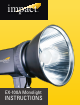
impact TM EX-100A Monolight INSTRUCTIONS
Thank you for your purchase of the Impact EX-100A Monolight. The EX-100A Monolight is economical and lightweight, yet durable enough to give you many years of trouble-free service and enjoyment. Please read these operating instructions and safety precautions carefully before operating this equipment.
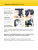
Preparing Your Monolight for Use Mount on a stand (1) Select a stand or support system of suitable weight and dimensions to ensure stable operation of the unit. Install Reflector & Modeling Lamp 1 2 3 4 (2) Remove the protective cap by pressing in and turning it counterclockwise. Pull the cap off and set aside. (3) Install the modeling lamp by screwing it into the threaded socket. CAUTION: Do not touch the lamp with your bare hands.
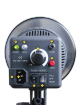
A D B C E F G H I
Operating Instructions Legend A – Recycle Indicator Light B – Photocell C – Power Regulator Dial D – Sync Jack E – Test Fire Button F G H I – Fuse Holder – Power Socket – On/Off Switch – Modeling Light Switch Power Supply Plug the power cord into the back of the flash unit. Before plugging the power cord into the wall socket, make certain that the power switch is set to the OFF (circle) position.
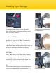
Flash Settings Flash Output The flash power output is variable over a three f/stop range (four f/stops) from full power to 1/8 power in a stepless gradation. Flash power is adjusted by rotating the power-regulator knob on the back panel of the unit. The EX-100A will sound a beep and the green indicator will light when the unit has recycled and is ready to flash. Lowering Flash Power While raising the flash power requires no special consideration, lowering the power does.
Modeling Light Settings The Modeling Light switch is to the right of the power switch and has three settings: Proportional Mode, Full Power, and Off. Modeling light and flash power are proportional Proportional Mode During normal use, most photographers will use a monolight in “Proportional” Mode. The modeling light intensity will increase or decrease in response to changes in the flash power.
Triggering the Flash TEST Button There are three ways to trigger your flash, but the simplest is to press the red TEST button. This is useful when you need to discharge the power built up in the flash unit, for example, just before replacing the flashtube (more on that later). Sync Connection The sync jack on the EX-100A Monolight may be used for direct connection to a camera set to ‘X’ synchronization.
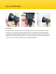
Use of Umbrellas Umbrellas An umbrella with a handle diameter of up to 9mm can be secured in the umbrella holder. Firmly press the umbrella shaft through the holder. The locking knob is located beneath the holder. Do not overtighten to avoid damaging the shaft of the umbrella. The reflector supplied with the Impact EX-100A features a slot through which you can feed the umbrella shaft. Be sure to install the reflector with the slot at the bottom.
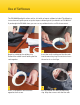
Use of Softboxes The EX-100A Monolight is often sold as a kit with an Impact softbox included. The following instructions will guide you to set up the Impact softbox typically included in an EX-100A kit. If you bought the EX-100A alone, you can use any softbox that has an Elinchrom mount. 1 Begin by unfolding the softbox skin. Remove the rubber bands holding the flex rods together. 3 Insert a second flex rod in the hole opposite the first one.
5 Tuck the thick end of one of the flex rods into a pocket in the corner of the softbox skin. 7 Continue with the third and fourth flex rods, inserting the small ends all the way into the mounting ring first. 6 Tuck the opposite flex rod into its pocket. You’ll have to bend the rod a little to get it to fit. 8 The interior baffle attaches with touch fasteners. You can leave this baffle off for more intense light.
Use of Softboxes (Continued) 9 The front diffuser attaches to touch fasteners on the outside edge of the softbox skin. 10 After you’ve attached the touch fasteners on all four sides, pull the corners of the diffuser over the corners of the softbox. 11 12 Mount your softbox onto the monolight. Line up the notches with the white marks, push in and turn clockwise until it locks. You’re ready to shoot. You can angle the softbox by releasing the locking arm. Adjust positioning, then lock it back down.
Breaking Down Your Softbox 1 Turn off the power to your light head and disconnect the power supply. Unmount the softbox assembly from the monolight. 3 The second rod to be released should be the one opposite the first. Continue with the third and fourth flex rods. 2 Remove both diffusers. Release a flex rod by folding the corner of the softbox away from its captured rod. 4 Pull the flex rods from the mounting ring. Stow everything until the next shoot.
Changing the Flashtube Discharge the Flash Unit The charge in the flash unit must be discharged before removing the flashtube. Make sure the flash unit is on. Push the TEST button on the rear panel of the flash. The unit will flash, discharging the power. Immediately turn off the power switch on the rear panel. Unplug the power cord from the power source. It is advisable to wait at least 30 minutes before touching or removing the flashtube.
Changing the Fuse A 6.3A fuse is mounted in the rear panel and protects the circuitry of the flash unit. Turn off the unit and disconnect the power supply before changing the fuse. Never replace with a fuse of a different type or rating. A spare 6.3A fuse has been included with your EX-100A monolight. Use a small screwdriver to release the fuse cover. Remove the old fuse, place the new fuse in the slot, then replace the fuse holder.
Safety and Maintenance Notes Safety Notes • Do not use your flash in an environment where moisture may come in contact with the unit. • A fire hazard exists if flammable materials are placed in close proximity to the flashtube or the modeling lamp. Do not use your flash in an environment where flammable vapors are present. • Do not restrict the ventilation holes when the flash is in use. • Always switch off the power and disconnect the power cord before changing the fuse, modeling lamp, or flashtube.
Best Practices As with any flash unit, the useful life of the flash tube and the unit as a whole depends on the way it is used. Avoiding excessive heat is the key to long life. • The fast recycling feature of the EX-100A allows a rapid sequence of high-power flashes. However, this feature should be used sparingly, since continuous rapid flashing can cause overheating and subsequent damage to the flashtube and possibly the internal electronics.
Specifications EX-100A Power Output Guide Number1 Output Control Range Recycling Time Flash Duration Flash Ready Indicator Modeling Lamp Triggers Trigger Voltage Built-in Slave Cell Color Temperature Flash Tube Reflector Mount Sync Cable Power Source Circuit Protection Dimensions Weight 100 W/S 30 Full power to 1/8 stepless 1~2 seconds 1/1000 ~ 1/1500 second LED and audible beep 60W (not to exceed 100W) Sync cable, slave sensor, test button 4.
One-Year Limited Warranty This IMPACT product is warranted to the original purchaser to be free from defects in materials and workmanship under normal consumer use for a period of one (1) year from the original purchase date or thirty (30) days after replacement, whichever occurs later.
GG2