nnel ver 2.
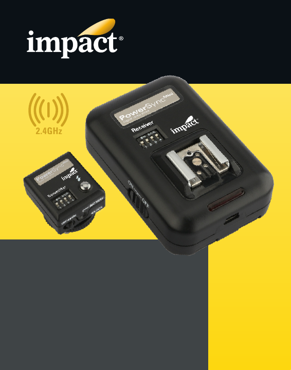
Introduction Thank you for choosing Impact. Impact’s PowerSync Mini is a sixteen-channel radio slave system that’s a reliable, professional-grade solution to remotely trigger portable on-camera flashes and studio monolights. Add additional receivers, and the PowerSync Mini system will control multi-light setups and allow you to trigger as many flash units as your setup requires.
Precautions • Please read and follow these instructions, and keep this manual in a safe place. • Keep this unit away from water and any flammable gases or liquids. • Do not attempt to disassemble or repair the equipment—doing so will void the warranty, and Impact will not be responsible for any damage. • The Impact PowerSync is an accessory device for flash photography. Do not use this product in a manner not specified within this documentation. • Use only the batteries recommended by this manual.
Overview PS16-Mini-R Receiver 4 1 3.
PS16-Mini-T Transmitter 11 Locking wheel 12 Channel selector 13 LED indicator 14 Test button 15 Mounting foot 16 Battery door release 17 Power switch 13 12 14 11 15 16 17 5
Overview PS16-Mini Accessories 18 1/4 in. adapter 19 3.
Installing the Batteries Receiver 1. Remove the receiver from its cradle. 2. Press the battery compartment lock and open the battery compartment door. 3. Place two AA batteries into the battery compartment, with the orientation shown in the diagrams inside the compartment. 4. Close the battery compartment door until it locks shut. Transmitter 1. Use the tip of a pen or the included lanyard pin tool to press the battery door release, and open the battery compartment door. 2.
Synchronizing Channels For the PowerSync system to work properly, the transmitter and receiver must be set to the same channel. The lanyard features a pin tool for changing the DIP switches. To set the channel, follow these steps: 1. Make sure both units are turned off. 2. Use the diagram below to set the DIP switches on the transmitter and receiver to the same configuration. Channel 3. Turn on the transmitter and receiver. 4. To test the setup, press the test button on the transmitter.
Setting Up the Transmitter 1. Slide the transmitter into your camera’s hot shoe. 2. The test button should be at the back, on the same side as the viewfinder. 3. Then tighten the locking wheel until secure.
Setting Up the Receiver With a Portable Flash Unit Slide the flash directly onto the receiver’s hot shoe. Remove the cradle to expose the 1/4-20 socket. You can now mount your flash directly onto a tripod, light stand, or mounting arm with a 1/4-20 screw. With a Monolight Use the flash sync cord to connect the receiver directly to the monolight’s sync socket. If the monolight has a 1/4 in. sync socket, use the included 1/4 in. adapter on one end of the sync cable.
Mounting the Receiver to a Monolight There are several ways to mount the receiver to a studio flash. Here are two common methods: • Attach the lanyard to the receiver via the lanyard hole, and hang the receiver on the light stand where your studio flash is mounted. • With the receiver in the cradle, remove the backing to expose the adhesive strips. Press the cradle onto your light’s chassis. The PowerSync’s effective range depends on the orientation and position of the transmitter and receiver.
Triggering a Remote Camera You can user your PowerSync Mini to trigger a remote camera. The camera must have an electronic shutter release connection, and you must have a compatible camera release cable (sold separately). 1. Connect the receiver to the electronic shutter release connection on your camera, using a compatible shutter release cable. 2. Make certain that the receiver and transmitter are set to the same channel and are powered up. 3.
Bulb Mode 1. Set your camera to bulb mode. 2. Half-press the test button to wake the camera or activate autofocus. 3. Fully press the test button to focus and open the camera’s shutter. 4. Release the test button to close the shutter and end the exposure. Bulb Lock Bulb lock lets you trigger the camera and leave the shutter open indefinitely without holding the test button. 1. Set your camera to bulb mode. 2. Press and hold the test button for three seconds to lock the shutter open.
Backward Compatibility The PowerSync Mini is backward compatible with Impact’s PowerSync 16 and PowerSync 16-80 systems. See the Backward Compatibility table for channel configurations. PowerSync Mini Transmitter to PowerSync 16-80 Receiver The PowerSync Mini transmitter can be used to trigger the PowerSync 16-80. Set the PowerSync 16-80 to Receiver (Rx) or Transmitter/Receiver (Tx/Rx) mode, and use the M button to accept a signal from the PowerSync Mini transmitter.
the PowerSync 16-80’s digital interface to set the corresponding channels. Backward Compatibility Mini Mini Important! The PowerSync 16-80 will work with the PowerSync 16 system only if No Group is selected on the PowerSync 16-80.
Accessories Your PowerSync Mini system is compatible with a wide variety of flash units right out of the box, but you may need an accessory sync cable for some flash units. Below are the plug ends commonly in use and the equipment they typically connect. Verify the plug compatible with your equipment. 1/8 in. (3.5 mm) Miniphoned 2.5 mm Sub-Miniphone Fits a wide variety of flashes. This plug is typically used only on slave systems 1/4 in.
Troubleshooting If the Transmitter and Receiver are not communicating with each other, try these common solutions. • If it’s a DC receiver, turn the receiver off, and verify that the batteries’ polarity is correct. Then turn the receiver back on. • Make sure the batteries in the Transmitter are fresh. Weak batteries will reduce the maximum transmission distance. • Ensure that both the transmitter and receiver are connected properly. • Make sure that both units are set to the same channel.
Specifications Wireless Channels: 16 Wireless Range: 328 ft. (100 m) Radio Frequency: 2.4 GHz General Sync Speed: 1/200 sec. Connectivity Ports: 3.5 mm sync Mini-USB Electrical Battery Type: PS16-Mini-T: CR2450 3 V PS16-Mini-R: AA 1.5 V (×2) Physical Dimensions: PS16-Mini-T: 1.2 × 1.2 × 1.4 in. (3.0 × 3.0 × 3.6 cm) PS16-Mini-R: 2.1 × 1.2 × 3.1 in. (5.4 × 3.1 × 8.0 cm) Weight: PS16-Mini-T: 1.0 oz. (28 g) PS16-Mini-R: 2.6 oz.
FCC Compliance This device complies with part 15 of the FCC rules. Operation is subject to the following two conditions: 1. This device may not cause harmful interference. 2. This device must accept any interference received, including interference that may cause undesired operation. Note: This equipment has been tested and found to comply with the limits for a Class B digital device, pursuant to part 15 of the FCC Rules.
One-Year Limited Warranty This Impact product is warranted to the original purchaser to be free from defects in materials and workmanship under normal consumer use for a period of one (1) year from the original purchase date or thirty (30) days after replacement, whichever occurs later.