POR TABL E AIR CON DITI ONE R Inside you will find many helpful hints on how to use and maintain your air conditioner properly. Just a little preventative care on your part can save you a great deal of time and money over the life of your air conditioner. Before operating this product, please read the instructions carefully and save this manual for future use.
CONTENTS SOCIABLE REMARK Sociable remark..................................................................................................................................2 SAFETY PRECAUTIONS Safety rules .......................................................................................................................................3 Operating condition ...........................................................................................................................3 Electrical information ..
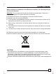
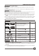
SOCIABLE REMARK When using this air conditioner in the European countries, the following information must be followed: DISPOSAL: Do not dispose this product as unsorted municipal waste. Collection of such waste separately for special treatment is necessary. It is prohibited to dispose of this appliance in domestic household waste.
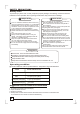
SAFETY PRECAUTIONS Safety rules To prevent injury to the user or other people and property damage, the following instructions must be followed. Incorrect operation due to ignoring of instructions may cause harm or damage. ! Always do this Your air conditioner should be used in such a way that it is protected from moisture. e.g. condensation, splashed water, etc. Do not place or store your air conditioner where it can fall or be pulled into water or any other liquid. Unplug immediately.
IDENTIFICATION OF PARTS WARNING For your safety Do not store or use gasoline or other flammable vapors and liquids in the vicinity of this or any other appliance. Avoid fire hazard or electric shock. Do not use an extension cord or an adaptor plug. Do not remove any prong from the power cord. Electrical Information WARNING Be sure the electrical service is adequate for the model you have chosen.
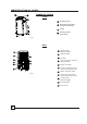
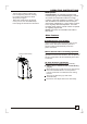
IDENTIFICATION OF PARTS 2 NAMES OF PARTS 1 Front 4 1 Operation panel 2 Horizontal louver blade (swing automatically) 3 Caster 4 Carrying handle (both sides) 3 Fig.1 Rear 5 6 Upper air filter (Behind the grille) 6 Upper air intake 7 Air outlet 8 Drain outlet (only for Pump heating model) 9 Power cord outlet 15 7 14 8 13 9 10 5 11 10 Power cord buckle (Used only when storing the unit) 12 11 Bottom tray drain outlet Fig.
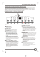
AIR CONDITIONER FEATURES ELECTRONIC CONTROL OPERATING INSTRUCTIONS Before you begin, thoroughly familiarize yourself with the control panel and remote controller and all its functions, then follow the symbol for the functions you desire. The unit can be controlled by the unit control panel alone or with the remote controller . NOTE: This manual does not include Remote Controller Operations, see the <> packed with the unit for details.
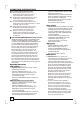
OPERATING INSTRUCTIONS Error codes and protection code: E1- Room temperature sensor errorUnplug the unit and plug it back in. If error repeats, call for service. E2- Evaporator temperature sensor errorUnplug the unit and plug it back in. If error repeats, call for service. E3- Conenser temperature sensor errorUnplug the unit and plug it back in. If error repeats, call for service. E4- Display panel communication errorUnplug the unit and plug it back in. If error repeats, call for service.
OPERATING INSTRUCTIONS - Turning the unit ON or OFF at any time or adjusting the timer setting to 0.0 will cancel the Auto Start/ Stop timer program. - When the malfunction (E1,E2,E3 or E4) occurs, the Auto Start/Stop timed program will also be cancelled. SLEEP operation Press this button, the selected temperature will O O increase(cooling) or decrease(heating) by 1 C/2 F 30 minutes.The temperature will then increase O O (cooling) or decrease (heating) by another 1 C/2 F after an additional 30 minutes.
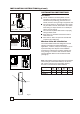
INSTALLATION INSTRUCTIONS(optional) INSTALLATION INSTRUCTIONS Location B A Fig.5 A:30cm-100cm B: 30cm Horizontal window The air conditioner should be placed on a firm foundation to minimize noise and virbration. For safe and secure positioning, place the unit on a smooth, level floor strong enough to support the unit. The unit has casters to aid placement, but it should only be rolled on smooth, flat surfaces. Use caution when rolling on carpet surfaces. Do not attempt to roll the unit over objects.
INSTALLATION INSTRUCTIONS(optional) Installation in a double-hung sash window Foam seal A (adhesive type) Fig.8 1. Cut the foam seal(adhesive type) to the proper length and attach it to the window stool. Fig.8 2. Attach the window slider kit to the window stool. Adjust the length of the window slider kit according to the width of window, shorten the adjustable window kit if the width of window is less than 26.5 (Type I) or 22.
INSTALLATION INSTRUCTIONS(optional) Installation in a sliding sash window Foam seal A (adhesive type) Fig.12 Window panel C 1. Cut the foam seal(adhesive type) to the proper length and attach it to the window frame. See Fig.12. 2. Attach the window slider kit to the window stool. Adjust the length of the window slider kit according to the width of window, shorten the adjustable window kit if the width of window is less than 26.5 (Type I) or 22.1 (Type II) inches.
INSTALLATION INSTRUCTIONS Exhaust hose installation: The exhaust hose and adaptor must be installed or removed in accordance with the usage mode. Fig.16a COOL,HEAT(heat pump type) or AUTO mode Fig.16b Install FAN,DEHUMIDIIFY or HEAT(electrical heat type) Remove mode Hole seat Hook Fig.17 1. Install the adaptor B and adaptor I onto the exhaust hose as shown in Fig.16a or Fig.16b. Refer to the previous pages for window kit installation. 2.
INSTALLATION INSTRUCTIONS Water drainage: Continuous drain hose - During dehumidifying modes, remove the upper drain plug from the back of the unit, install the drain connector(5/8 universal female mender) with 3 4 hose(locally purchased). For the models without drain connector, just attach the drain Remove the upper drain plug drain hose adaptor hose to the hole. Place the open end of the hose adaptor directly over the drain area in your basement floor. Please refer to Fig.20a. Fig.
CARE AND MAINTENANCE CARE AND MAINTENANCE Upper filter (take out) Remove the screw ,then take the lower filter out. Fig.23 Upper filter (install) IMPORTANT: 1) Be sure to unplug the unit before cleaning or servicing. 2) Do not use gasoline, thinner or other chemicals to clean the unit. 3) Do not wash the unit directly under a tap or using a hose. It may cause electrical danger. 4) If the power cord is damaged, it should be repaired by manufacture or its agency. 1.
TROUBLESHOOTING TIPS TROUBLE SHOOTING TROUBLES POSSIBLE CAUSES SUGGEST REMEDIES 1. Unit does not - P1 appears in the display window Drain the water in the bottom tray. Start when Pressing on/off Button - Room temperature is lower than the set temperature.(Cooling mode) - The windows or doors in the room are not closed. 2. Not cool enough - There are heat sources inside the blocked. doors are closed. Remove the heat sources if possible. Connect the duct and make sure it can function properly.
The design and specifications are subject to change without prior notice for product improvement. Consult with the sales agency or manufacturer for details.