
Owner's Manual
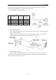
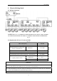
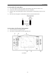
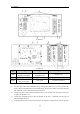
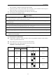
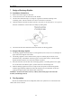
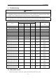
Table Of Contents

BU Module
17
6 Electrical Wiring Work
6.1 Wiring Connection
NOTICE! The “L1”, “3” terminals are connected to the live wire, the “L2”,”N(1)” terminals
are connected to the neutral wire and the ”2” terminal is connected to the transmission line.
Fig. 24
6.2 Requirements of Power Circuit and Cable
Table 11
Phase and frequency 1Ph,60Hz
Voltage 208/230V
Recommended cable of outdoor unit
(Pieces × Sectional area)
3×6.0 mm
2
ISMO-6021
Recommended cable of BU module (Pieces × Sectional area) 3×0.75 mm
2
Transmission line (Pieces × Sectional area) 2×1.5 mm
2
Recommended cable of indoor unit (Pieces × Sectional area) 4×0.75mm
2
Capacity of the air switch
ISMO-6021
40A
BU module 10A
NOTICE
1) The total length of the transmission line between the outdoor unit and the furthest BU module is not
more
than 180 feet (55m). Otherwise, the system cannot work possibility.
2) The specifications of the power cable and transmission line listed in the table above are determined
based on the maximum power (maximum amps) of the unit.
3) The specifications of the power cable listed in the table above are applied to the conduit-guarded