
Owner's Manual
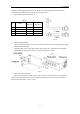
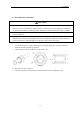
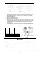
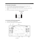
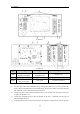
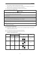
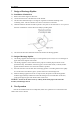
Table Of Contents

BU Module
20
b
) IS-BU13
c) IS-BU15
NO. 1 2 3
Name
Terminal black for BU
module power supply
Terminal black for
transmission line
Ground screw
NO. 4 5 6
Name
Terminal black for indoor
unit power supply
DIP switch Printed circuit board
Fig. 26
3) Let the power cable and transmission line go through the rubber ring. In order to protect the
power cable and transmission line from damaging by the hole, the rubber ring cannot fall from
that, otherwise, it may cause electrical shock or fire etc.
4) Connect the power cable of the BU module to the L1, L2 terminals with the sign of Power and
as well as the ground screw.
5) Connect the transmission line of the BU module to the N(1), 2 terminals with the sign of
Outdoor unit/BU module.
6) If the transmission line need to be connected to the other BU module, please connect the extra