Impecca Through-the-Wall Air Conditioner Users Manual ITAC-08KS • ITAC-10KSA20 (115V) • ITAC-12KSA20 (115V) ITAC-14KS • ITAH-08KR • ITAH-10KR • ITAH-12KR • ITAH-14KR 1
Table of Contents: – Introduction . . . . . . . . . . . . . . . . . . . . . . . . . . . . . . . . . . . . . . . . . . . . . . . . . . . . . . . . . . . . . . . . . . . . . . . . . . . . . . . . . . . . . . p.1 – Safety Notices. . . . . . . . . . . . . . . . . . . . . . . . . . . . . . . . . . . . . . . . . . . . . . . . . . . . . . . . . . . . . . . . . . .
Introduction: Congratulations on your purchase of an IMPECCA™ Electronic Controlled Portable Air Conditioner. Before using this product, it is recommended that you familiarize yourself with the features, functions, and operating procedures described in this manual. Inside you will find many helpful hints on how to use and maintain your air conditioner properly. Just a little preventive care on your part can save you a great deal of time and money over the lifespan of your air conditioner.
READ THESE NOTICES CAREFULLY—THEY ARE IMPORTANT! WARNING ⍟ Plug in power plug properly. • Otherwise, it may cause electric shock or fire due to excess heat generation. ⊘ Do not modify power cord length or share the outlet with other appliances. • It may cause electric shock or fire due to heat generation. ⍟ Always ensure effective grounding/earthing. • Incorrect grounding may cause electric shock. ⍟ Unplug the unit if strange sounds, smells, or smoke comes from it. • It may cause fire and electric shock.
CAUTION ⍟ Stop operation and close the window in storm or hurricane. ⍟ Hold the plug by the head of the power plug when unplugging unit. • Operation with windows opened may cause wetting of indoor and soaking of household furniture. ⊘ Do not place obstacles around air-inlets or inside of air-outlet. • Otherwise, it may cause electric shock and damage. ⊘ Ensure that the installation bracket of the outdoor appliance is not damaged due to prolonged exposure. • It may cause failure of appliance or accident.
What’s In the Box: Please verify your box for the following items. Note that some models may not include all items. ❷ ❶ ❸&❹ 1. Air Conditioning Unit 2. Remote control (may differ from photo) 3. User’s Guide 4. Remote control user’s guide 5. Installation kit (see details below) Installation Accessory Kit Items: TOOLS REQUIRED: large flat blade screwdriver, tape measure, adjustable wrench or pliers, pencil, level, socket wrenches, and Phillips screwdriver. NOTE: You may not need all listed parts.
Operating Your Air Conditioner: Before you begin, thoroughly familiarize yourself with the control panels as shown below and all its functions, then follow the symbol for the functions you desire. The unit can be controlled by the unit control alone or with the remote. Note: This illustration is for explanation purposes only. The actual appearance of the control panel on the air conditioner you bought may be slightly different. Turning the Unit On or off: • Press the On/Off Button.
Fan Only Mode: • Use this mode when you’d like to circulate air or exhaust stale air but not run the air conditioner. • Open the vent in fan mode, but for most efficiency keep it closed during cooling mode. • The display shows the ambient room temperature. Timer & AUto Start/stop Feature: • The timer indicator lights are for two separate functions, one to automatically turn the unit on and another to automatically shut it off. Both programs can be set at the same time.
Check Filter Feature: • The indicator light illuminiates automatically after 250 hours of operation to help you maintain optimum performance. • To reset after cleaning the filter, press the Check Filter button and the light will turn off. Fresh Air Vent Control (Some Models) The fresh air vent allows the air conditioner to: 1. Recirculate inside air—vent closed (image 1) 2. Draw fresh air in the room—vent open (image 2) 3.
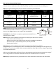
PRE-Installation Instructions: Please read ALL instructions before installing. Two people are recommend to install this product. If a new electrical outlet is required, have the outlet installed by a qualified electrician before installing unit. Step 1) Using the following table, find your wall-sleeve brand of your installation.
READ CAREFULLY—IMPORTANT IMPORTANT This units increased performance characteristics result from having two rear air intakes. It is very important that these installation instructions are followed so your unit can operate at maximum efficiency. If this is an existing sleeve, and there is an existing rear grille, it needs to be replaced by one that has been shipped with the unit in the accessory kit.
N° 1:Wall Emerson 15” Deep Wall Sleeves Sleeve Brands: 4 3 8 8 3 4 #1 Emerson 15 Deep 1. Remove existing rear rear grille as shown page 9on ofPage this 1. Remove existing grille ason shown manual andmanual replace and with provided rear panel. 11 of this replace louvered with provided Install as shown louvered rear here. panel. Install as shown here. NOTE: You may need to drill holes in flange of existing sleeve to match new rear grille. 2 4 4 2.
N° 2:Wall Fedders 19¾” Deep Wall Sleeves Sleeve Brands: 4 3 8 8 3 4 #2 Fedders 193/4 Deep 1. existing rear grille shownas onshown page 9 on of this Remove existing rearasgrille Page 1.Remove manual and replace withand provided louvered panel. 11 of this manual replace with rear provided louvered Install as shownrear here.panel. Install as shown here. NOTE: You may need to drill holes in flange of existing sleeve to match new rear grille. 2.
N° 3: Fedders/Friedrich 16¾” Deep Wall Sleeves Wall Sleeve Brands: 4 3 8 8 3 4 163/4 Deep #3 Fedders or Friedrich 1. Remove existing rearrear grille grille as shown page on 9 ofPage this 1.Remove existing as on shown 11 of this and provided replace louvered with provided manual andmanual replace with rear panel. louvered rearhere. panel. Install as shown here. Install as shown NOTE: You may need to drill holes in flange of existing sleeve to match new rear grille. 2.
N° 4: General Electric/HotpOint 16⅞” Deep Wall Sleeves Wall Sleeve Brands: 4 3 8 8 3 4 #4 General Electra/Hotpoint 167/8 Deep 1. existing rear grille shown page 9on of Page this 1.Remove Remove existing rear as grille ason shown 11 of this and provided replace louvered with provided manual andmanual replace with rear panel. louvered rearhere. panel. Install as shown here. Install as shown NOTE: You may need to drill holes in flange of existing sleeve to match new rear grille. 2.
N° 5:Wall Sears–Kenmore/Carrier 51S 18⅝” Deep Wall Sleeves Sleeve Brands: #5 Sears or Carrier 51S Series ( 185/8 Deep) 4 3 8 8 3 4 1. existing rear grille shown page 9on of Page this 1.Remove Remove existing rear as grille ason shown manual and replace with provided louvered rear panel. 11 of this manual and replace with provided Install as shown louvered rearhere. panel. Install as shown here. NOTE: You may need to drill holes in flange of existing sleeve to match new rear grille. 2.
N° 6:Wall Whirlpool 17⅛”Brands: Deep Wall Sleeves Sleeve 4 3 8 8 3 4 #6 Whirlpool 171/8 Deep Remove existing rear asgrille Page 1.1.Remove existing rear grille shownasonshown page 9on of this 11 of this manual and replace with provided manual and replace with provided louvered rear panel. louvered rearhere. panel. Install as shown here. Install as shown NOTE: You may need to drill holes in flange of existing sleeve to match new rear grille. 2.
N° 7: Whirlpool 23” Deep Wall Sleeves Wall Sleeve Brands: 4 3 4 5 8 8 3 #7 Whirlpool 1. existing rear grille shown page 9on of Page this 1.Remove Remove existing rear as grille ason shown manual and replace with provided louvered rear panel. 11 of this manual and replace with provided Install as shown louvered rearhere. panel. Install as shown here. 4 4 6 7 7 14 10 11 4 9 13 4 ( 23 Deep) 12 NOTE: You may need to drill holes in flange of existing sleeve to match new rear grille.
N° 8: Westinghouse/Carrier 52F 16 & 17” Deep Wall Sleeves Wall Sleeve Brands: 4 3 8 8 3 4 #8 White Westinghouse/Frigidaire/ Carrier 52F Series ( 16 +171/2 Deep) 1. Remove existing rear rear grille as shown page 9on ofPage this 1.Remove existing grille ason shown manual and replace with provided louvered rear panel. 11 of this manual and replace with provided Install as shown louvered rearhere. panel. Install as shown here.
N° 9: White/Westinghouse Frigidaire 22” Deep Wall Sleeves #9 White Westinghouse or Frigidaire Wall Sleeve Brands: ( 22 Deep) 4 7 3 4 8 8 1. existing rear grille shown page 9on of this Remove existing rear asgrille asonshown Page 1.Remove manual and replace with provided louvered rear panel. 11 of this manual and replace with provided louvered Install as shownrear here.panel. Install as shown here.
Direct Mounting Instructions: Direct Unit Mounting: The previous directions are the preferable way to mount the new rear grill. The units performance is slightly better and the possibility of draughts is reduced. As a last resort, direct mounting of the grille to the unit can be considered. Note: The grille must be installed prior to inserting the unit into the sleeve. 1. Attach the 2 seal pieces (1 X3/8 X14 ) as shown in Fig. 1. 2.Position the grille over the rear of the unit making sure that: a.
Sealing Instructions: FINISHING INSTALLATION: 1. Install the 1 x11/2 x84 long stuffer-seal between the wall-sleeve and the unit. A flat-bladed screwdriver or putty knife is recommended. 2. Assemble the trim frame by inserting top and bottom pieces into side pieces and snapping into place. 3. Pull cord through trim frame then slide over unit until flush with wall.
Care & Cleaning: CARE AND CLEANING CAUTION CAUTION Clean your air conditioner occasionally to keep it looking new. Clean your air conditioner occasionally to keep it looking new. Be sure to unplug the unit Be sure to unplug the unit before cleaning to prevent shock or fire hazards. before cleaning to prevent chock or fire hazards. Air Filter Cleaning The air filter should be checked at least once a month to see if cleaning is necessary.
Troubleshooting Tips: TROUBLESHOOTING TIPS Save Time and money! If youcalling review chart of Troubleshooting Tips not This need call forcommon service at all. Before forour service, review this list. It may save youfirst, timeyou and may expense. listtoincludes occurrences that are not the result of defective workman-ship or materials in this appliance. Problem Solution Air conditioner does not start Wall plug disconnected. Push plug firmly into wall outlet.
Troubleshooting Tips: Problem Solution Unit removing large quantity of moisture from humid room. This is normal during excessively humid days. Water dripping OUTSIDE when unit is cooling. Remote control not located within range. Place remote control within 20 feet & 180 , radius of the front of the unit. Remote Sensing Deactivating Prematurely (some models) Remote control signal obstructed. Remove obstruction. Set temperature too low. Increase set temperature.
Impecca Through-the-Wall Air Conditioner Users Manual ITAC-08KS • ITAC-10KSA20 (115V) • ITAC-12KSA20 (115V) ITAC-14KS • ITAC-08KR • ITAC-10KR • ITAC-12KR • ITAC-14KR 1
Table of Contents: – Introduction . . . . . . . . . . . . . . . . . . . . . . . . . . . . . . . . . . . . . . . . . . . . . . . . . . . . . . . . . . . . . . . . . . . . . . . . . . . . . . . . . . . . . . p.1 – Safety Notices. . . . . . . . . . . . . . . . . . . . . . . . . . . . . . . . . . . . . . . . . . . . . . . . . . . . . . . . . . . . . . . . . . .
INTRODUCCIÓN: Felicitaciones por su compra de un Aire Acondicionado Portátil Controlado Electrónicamente Impecca™. Antes de utilizar este producto, se recomienda que se familiarice con las características, funciones y procedimientos operativos descritos en este manual. En su interior encontrará muchos consejos útiles sobre cómo utilizar y conservar su aire acondicionado. Un poco de cuidado preventivo de su parte puede ahorrarle mucho tiempo y dinero durante la vida útil de su aire acondicionado.
LEA CUIDADOSAMENTE ESTOS AVISOS—SON IMPORTANTES! ADVERTENCIA ⍟ Conecte el enchufe de forma adecuada. • De no hacerlo puede causar una descarga eléctrica o fuego debido a la generación de calor. ⊘ No modifique la longitud del cable alimentación o comparta el tomacorriente con otros aparatos. • Puede causar una descarga eléctrica o fuego debido a la generación de calor. ⍟ Asegúrese que siempre exista la adecuada conexión a tierra en el tomacorriente.
PRECAUCIONES ⍟ Detenga la operación y cierre la ventana en caso de huracán o tormenta. ⍟ Sostenga firmemente el enchufe del cable de alimentación cuando desconecte la unidad. • La operación con las ventanas abiertas puede causar que el interior se anegue y se mojen los muebles de la habitación. • De no hacerlo puede causar daños y descarga eléctrica. ⊘ No coloque obstáculos alrededor de las entradas de aire o dentro de las salidas de aire.
QUE VIENE EN LA CAJA: Verifique las siguientes piezas en la caja. Tome en cuenta que algunos modelos pueden no incluir todas las piezas. ❷ ❸&❹ 1. Unidad de Aire Acondicionado 2. Control Remoto (Puede ser un poco diferente al mostrado en la imagen) 3. Manual de Usuario 4. Manual de Usuario del Control Remoto 5.
PONIENDO EN FUNCIONAMIENTO SU AIRE ACONDICIONADO: Antes de continuar familiarícese ampliamente con el panel de control y sus funciones que se muestran a continuación, después siga el símbolo para la función deseada. La unidad puede ser controlada mediante el panel de control al frente de la unidad o por el control remoto. Modelos de Sólo Enfriamiento Modelos con Calefacción y Enfriamiento NotA: El motivo de esta ilustración es para explicación.
MODO FAN ONLY (VENTILADOR): TEMPORIZADOR Y FUNCIONES DE AUTO START/ AUTO STOP (INICIO Y PARO AUTOMÁTICOS): • Utilice esta función cuando no desee enfriar la habitación sino solamente hacer circular el aire o para sacar el aire viciado. • Abra el respiradero durante esta función, pero manténgalo cerrado durante el modo COOL (enfriar) para una mayor eficiencia. • La pantalla mostrará la temperatura ambiente de la habitación.
FUNCION DE REVISION DEL FILTRO: • Para ayudarle a que conserve un despeño óptimo la luz indicadora CHECK FILTER se iluminará luego de 250 horas de operación. • Para restaurar luego de limpiar el filtro presione el botón Check Filter y la luz se apagará. CONTROL DE VENTILAS PARA AIRE FRESCO (SOLO CIERTOS MODELOS) Las ventilas de aire fresco permiten que el aire acondicionado: 1. Recircule el aire interior—ventila cerrada (imagen 1) 2. Enviar aire fresco a la habitación —ventilas abierta (imagen 2) 3.
INSTRUCCIONES DE INSTALACIÓN PREVIA Por favor lea TODAS las instrucciones antes de instalar. Se recomiendan dos personas para instalar este producto. En caso de requerirse un tomacorriente eléctrico nuevo, este debe ser instalado por un electricista calificado antes de instalar la unidad. Paso 1) Usando la siguiente tabla, encuentre el soporte de pared para su instalación.
READ CAREFULLY—IMPORTANT IMPORTANT • Las características del rendimiento incrementado de esta unidad se deben a que cuenta con dos de aire en la parte posteThis units increased performance characteristics result from having two rear air tomas intakes. rior. It is very important that these installation instructions are followed so your unit can operate at • Es muy importante seguir estas instrucciones de instalación de manera que su unidad opere con una eficiencia máxima maximum efficiency.
N° 1:Wall SOPORTES DE PARED Emerson 15” Sleeve Brands: 4 3 8 8 3 4 #1 Emerson 15 Deep 1. Retire la parrilla posteriorrear existente se muestra en la pági1. Remove existing grillecomo as shown on Page na 911 deofeste manual y reemplácela conwith la rejilla de persianas que this manual and replace provided vinolouvered con su unidad. se as muestra aquí. rear Instale panel.como Install shown here.
N° 2:Wall SOPORTES DE PARED Fedders 19¾” Sleeve Brands: 4 3 8 8 3 4 #2 Fedders 193/4 Deep 1. la parrilla posterior existente como se muestra en la págiRemove existing rear grille as shown on Page 1.Retire na 911 deof este manual y reemplácela con with la rejilla de persianas que this manual and replace provided rearInstale panel.como Install as shown here. vinolouvered con su unidad. se muestra aquí.
N° 3: SOPORTES DE PARED Fedders/Friedrich 16¾” Wall Sleeve Brands: 4 5 3 4 8 8 3 4 4 #3 Fedders or Friedrich 163/4 Deep 1. Retire la parrilla posteriorrear existente se muestra en la pági1.Remove existing grillecomo as shown on Page na 911 deofeste manual y reemplácela con la rejilla de persianas que this manual and replace with provided vinolouvered con su unidad. se as muestra aquí. rear Instale panel.como Install shown here.
N° 4: SOPORTES DE PARED General Electric/HotpOint 16⅞” Wall Sleeve Brands: 4 3 8 8 3 4 #4 General Electra/Hotpoint 167/8 Deep 1. Remove Retire la parrilla posterior se muestra en la pági1. existing rear existente grille ascomo shown on Page na 9 de este manual y reemplácela con la rejilla de persianas que 11 of this manual and replace with provided vino con surear unidad. Instale como muestrahere. aquí. louvered panel.
N° 5:Wall SOPORTES DE PARED Sears–Kenmore/Carrier 51S 18⅝” Sleeve Brands: #5 Sears or Carrier 51S Series ( 185/8 Deep) 4 3 8 8 3 4 Remove existing rear grille as shown on Page (18 1. 5/8” De Profundidad) 11 of this manual and replace with provided louvered rear panel. existente Install ascomo shown here. en la pági1. Retire la parrilla posterior se muestra na 9 de este manual y reemplácela con la rejilla de persianas que You may need to drill holes inaquí. flange of vinoNOTE: con su unidad.
N° 6:Wall SOPORTES DE PARED Whirlpool 17⅛” Sleeve Brands: 4 3 8 8 3 4 #6 Whirlpool 171/8 Deep 1.Retire Remove existing rearexistente grille as shown on Page 1. la parrilla posterior como se muestra en la pági11 of this manual and replace with provided na 9 de este manual y reemplácela con la rejilla de persianas que louvered rear panel. Install shown here. vino con su unidad. Instale comoas se muestra aquí.
N° 7: SOPORTES DE PARED Whirlpool 23” Wall Sleeve Brands: 4 3 4 5 8 8 3 1. Retire la parrilla posterior existente como se muestra en la pági#7 Whirlpool ( 23 Deep) na 9 de este manual y reemplácela con la rejilla de persianas que vino con su unidad. Instale como se muestra aquí. 1. Remove existing rear grille as shown on Page NOTA: Talthis vez requiera orificioswith en los rebordes de la 11 of manualperforar and replace provided carcasa existente para coincidir con la nueva rejilla.
N° 8: SOPORTES DE PARED Westinghouse/Carrier 52F 16 & 17” Wall Sleeve Brands: 4 2 3 4 8 8 3 3 4 4 4 #8 White Westinghouse/Frigidaire/ 1/2 Carrier 52F Series ( 16 +17 Deep) 1. Retire la parrilla posterior existente como se muestra en la página 9 de este manual y reemplácela con la rejilla de persianas que 1.Remove existing rearcomo grille as shown on Page vino con su unidad. Instale se muestra aquí.
N° 9: SOPORTES DE PARED White/Westinghouse Frigidaire 22” #9 White Westinghouse or Frigidaire Wall Sleeve Brands: 1. Retire(la22 parrilla posterior existente como se muestra en la págiDeep) 4 7 3 4 8 8 na 1. 9 de este manual y reemplácela con la de persianas Remove existing rear grille asrejilla shown on Pageque vino con su unidad. Instale como se muestra aquí. 11 of this manual and replace with provided rear perforar panel. Install here.
INSTRUCCIONES DE MONTAJE DIRECTO: Direct Unit Mounting: Las instrucciones anteriores refieren al modo preferente way de montar la nueva rejillarear posterior. desempeño de la unidad is es The previous directions are the preferable to mount the new grill. ElThe units performance ligeramente mejor y la posibilidad de las corrientes de aire se reduce. Como un último recurso, se puede considerar el montaslightly better and the possibility of draughts is reduced.
INSTRUCCIONES DE SELLADO: FINISHING INSTALLATION: 1. la junta relleno de 1” x 1 ½”between x 84 de 1. Instale Install the 1 x11/2de x84 long stuffer-seal the entre wall-sleeve and ythe A flat-bladed largo la carcasa la unit. unidad. Se recomienda screwdriver or putty knife is orecommended. utilizar un desarmador plano una espátula. 2.2.
LIMPIEZA Y CUIDADOS: CARE AND CLEANING PRECAUCIONES CAUTION Limpie su aire acondicionado ocasionalmente para mantenerlo como nuevo. Asegúrese de desconectar Clean your air conditioner occasionally to keep it looking new. Be sure to unplug the unit la unidad antes de la limpieza para evitar descargas eléctricas o peligro de incendio. before cleaning to prevent chock or fire hazards.
CONSEJOS PARA SOLUCIONAR PROBLEMAS: Problema Solución • La unidad puede estar desconectada. Empuje firmemente el enchufe en el tomacorriente • El fusible de la casa se ha quemado o se disparó el cortacorriente. Reemplace el fusible con uno de tipo de retraso o restablezca el cortacorriente. No enciende el aire acondicionado. • Conecte el aparato y presione el botón RESET. • El control está apagado (OFF). Encienda el control (ON) y ajuste como desee.
CONSEJOS PARA SOLUCIONAR PROBLEMAS: Problema Solución Agua goteando POR FUERA cuando la unidad está enfriando. • La unidad está retirando una gran cantidad de humedad de una habitación húmeda. Esto es normal durante días excesivamente húmedos. • La temperatura de la habitación está por debajo de los 17°C (62° F). No puede comenzar el enfriamiento hasta que la temperatura de la habitación sea superior a los 17° C (62° F).