NOTE: Please read all instructions carefully before using this product Safety Notice MARCY HOME GYM Hardware Identifier Assembly Instruction APEX II Parts List Resistance Chart Warranty Ordering Parts Model APEX II Retain This Manual for Reference 08-14-01 OWNER'S MANUAL IMPEX FITNESS PRODUCTS 14777 DON JULIAN RD., CITY OF INDUSTRY, CA 91746 Tel: (800) 999-8899 Fax: (626) 961-9966 www.impex-fitness.com info@impex-fitness.
TABLE OF CONTENTS BEFORE YOU BEGIN....................................................................................……….. 1 IMPORTANT SAFETY NOTICES...................................................................……….. 2 HARDWARE IDENTIFIER.....….....................................................................……….. 3 ASSEMBLY INSTRUCTIONS.........................................................................……….. 4 HOW TO USE.........................................................................
IMPORTANT SAFETY NOTICE PRECAUTIONS This exercise machine is built for optimum safety. However, certain precautions apply whenever you operate a piece of exercise equipment. Be sure to read the entire manual before you assemble or operate your machine. In particular, note the following safety precautions: 1. Keep children and pets away from the machine at all times. DO NOT leave children unattended in the same room with the machine. 2. Only one person at a time should use the machine. 3.
3
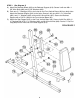
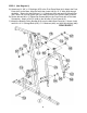
ASSEMBLY INSTRUCTION Tools Required Assembling the Machine: Two Adjustable Wrenches, two Allen Wrenches, and one Flat Head Screwdriver. NOTE: It is strongly recommended this machine to be assembled by two or more people to avoid possible injury. STEP 1 (See Diagram 1) A.) Connect the Main Base Frame (#1) and Rear Vertical Beam (#4) to the Rear Stabilizer (#9). Align the holes then secure them with two M10 x 2 ¾” Carriage Bolts (#79), ∅ ¾” Washers (#94), and M10 Aircraft Nuts (#96).
STEP 2 (See Diagram 2) A.) Place two Rubber Bumpers (#72) onto the Main Base Frame (#1). Align the holes and push two Guide Rods (#8) through the Bumpers into the Main Base Frame (#1). B.) Install fourteen Weight Plates (#42). To install the plate, hold the plate at an angle and place it in between the two Guide Rods then drop it down. NOTE: Make sure the groves on the plastic covers all face up. Insert the Selector Rod (#41) into the center hole on the plates.
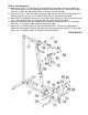
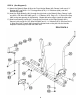
STEP 3 (See Diagram 3) A.) Attach the Backrest Board (#23) to the Backrest Support (#16). Secure it with two M8 x 1 5/8” Allen Bolts (#89) and ∅ 5/8” Washers (#93). B.) Push two ∅ 1” Bushings (#70) to the holes on the Front Vertical Beam (#2) from both sides. Attach the Backrest Support (#16) to the holes. Secure it with one M12 x 3 ½” Allen Bolt (#80), two ∅ 1” Washers (#95), and one M12 Aircraft Nut (#97). Secure the Backrest Support with a Pull Pin (#48) on the Front Vertical Beam (#2). C.
STEP 4 (See Diagram 4) A.) Attach two ∅1 5/8” x ¼” Bushings (#76) to the holes on the Upper Frame (#3). Attach the Front Press Base (#14) to the Bushings. Align the holes then insert a 7” Axle (#33) through the holes. Secure the Axle with two M6 x ¼” Slotted Set Screws (#92). B.) Insert a M10 x 6 ¾” Allen Bolt (#84) through the upper holes on the Front Press Base (#14). Securely tighten it with two ∅ ¾” Washers (#94) and one M10 Aircraft Nut (#96). C.
STEP 5 (See Diagram 5) A.) Attach two ∅1 5/8” x ½” Bushings (#75) to the Front Press Base (#14). Attach the Front Press (#15) to the Base. Align the holes then insert a M12 x 10 ¾” Axle (#34) through the holes. Secure the Axle with two ∅ 1 ¼” Washers (#74) and two M12 Aircraft Nuts (#97). Note: Do not over tighten the nuts. Make sure the Front Press Is able to Swivel. B.) Secure the two M6 x ¼” Slotted Set Screws (#92) on the Front Press with a Flat Head Screwdriver.
STEP 6 (See Diagram 6) A.) Attach the Butterfly Base (#18) to the Front Vertical Beam (#2). Secure it with one 4 ¾” Bracket (#27), two M10 x 3 ½” Carriage Bolts (#78), ∅ ¾” Washers (#94), and M10 Aircraft Nuts (#96). B.) Insert the Right Butterfly (#21) through the right hole on the Butterfly Base. Secure it with one M12 x 5/8” Allen Bolt (#83) and ∅ 1 ½” Washer (#73). Plug a ∅1 ½” Round End Cap (#63) to the end opening on the Butterfly. Repeat the same step to install the other side. C.
STEP 7 (See Diagram 7) A.) Place the Seat Pad (#22) onto the Seat Post (#13). Secure it with two M8 x 1 5/8” Allen Bolts (#89) and ∅ 5/8” Washers (#93). Insert the Seat Post (#13) into the opening on the Seat Support (#10). Thread a Lock Knob (#49) on the Seat Support (#10) to obtain the desired height of the Seat. B.) Insert one Foam Roll Tube (#30) halfway through the hole on the Seat Post (#13). Insert one Foam Roll Tube (#30) halfway through the hole on the Leg Developer (#12).
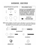
CABLE LOOP DIAGRAM 11
STEP 8 (See Diagram 8 & Cable Loop Diagram) A.) Attach the 174” Upper Cable (#36) to the opening at the front of the Upper Frame (#3). Note: The Ball Stopper on the cable should be underneath the Frame. B.) Attach a Pulley (#50) to the slotted opening. Then attach two ∅7/8” x 5/8” Pulley Bushings (#67) to the holes on both sides. Align the holes and secure it with one M10 x 2 ½” Allen Bolt (#85) and M10 Aircraft Nut (#96). C.) Draw the Cable towards the back of the machine to the opening on the Upper Frame.
DIAGRAM 8 13
STEP 9 (See Diagram 9 & Cable Loop Diagram) A.) Attach the 169” Lower Cable (#38) to the opening on the Leg Developer (#12). Place a Pulley (#50) in the opening. Secure it with one M10 x 2 3/8” Allen Bolt (#86), two ∅7/8” x ½” Pulley Bushings (#68), and one M10 Aircraft Nut (#96). B.) Draw the Cable underneath the Pulley and towards the back of the machine to the open bracket on the Main Base Frame (#1).
DIAGRAM 9 15
STEP 10 (See Diagram 10 & Cable Loop Diagram) A.) Attach one end of the 87” Butterfly Cable (#37) to the clip on the Right Butterfly (#21). Draw the Cable to the right open bracket on the Butterfly Pulley Bracket (#19). B.) Attach a Pulley to the Bracket and secure it with one M10 x 1 ¾” Allen Bolt (#87), two ∅ ¾” Washers (#94), one 2 7/8” L-shaped Bracket (#98), and one M10 Aircraft Nut (#96). C.
STEP 11 (See Diagram 11) A.) Attach a Long Chain (#45) to the Upper Cable (#36). Attach the Lat Bar (#26) to the Chain using a C-clip (#44). Adjust the length of the Chain to obtain desired Lat Bar exercise position. See How to Use on page 18. B.) Attach a Long Chain (#45) to the Lower Cable (#38). Attach the Arm Curl Handle (#31) to the Chain using a C-clip (#44). Adjust the length of the Chain to obtain the desired Arm Curl exercise position. Remove the Chain and the Handle when using the Leg Developer.
HOW TO USE How to use the quick release connector. The Clip is removed from the Connector. Connector Clip Place the chain in between the connector and insert the Clip through the holes. Chain Insert Push down the Clip to secure.
PARTS LIST KEY NO.
20
IMPEX INC. LIMITED WARRANTY IMPEX Inc. ("IMPEX") warrants this product to be free from defects in workmanship and material, under normal use and service conditions, for a period of two years on the Frame from the date of purchase. This warranty extends only to the original purchaser. IMPEX's obligation under this Warranty is limited to replacing or repairing, at IMPEX's option. All returns must be pre-authorized by IMPEX.