
Owner's Manual

ASSEMBLY INSTRUCTION
Tools Required Assembling the Machine: Two Adjustable Wrenches, two Allen Wrenches,
and one Flat Head Screwdriver. NOTE: It is strongly recommended this machine to be
assembled by two or more people to avoid possible injury.
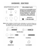
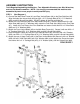
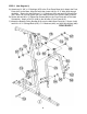
STEP 1 (See Diagram 1)
A.) Connect the Main Base Frame (#1) and Rear Vertical Beam (#4) to the Rear Stabilizer (#9).
Align the holes then secure them with two M10 x 2 ¾” Carriage Bolts (#79), ∅ ¾” Washers
(#94), and M10 Aircraft Nuts (#96). DO NOT tighten all the nuts and bolts yet.
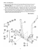
B.) Attach the Front Stabilizer (#6) to the Main Base Frame (#1). Secure it with three M10 x 5/8”
Allen Bolts (#88) and ∅ ¾” Washers (#94). Insert the Foot Plate Axle (#99) into the Foot Plate
(#7). Attach the Foot Plate to the Front Stabilizer and secure it with two M10 x ¾” Allen Bolts
(#82) and ∅ ¾” Washers (#94).
C.) Attach the Front Vertical Beam (#2) to the Main Base Frame (#1). Secure it with two M10 x 2
¾” Carriage Bolts (#79), ∅ ¾” Washers (#94), and M10 Aircraft Nuts (#96).
D.) Place the Upper Frame (#3) onto the Front Vertical Beam (#2). Secure it with a 6¼” Bracket
(#29), two M10 x 2 ¾” Carriage Bolts (#79), ∅¾” Washers (#94), and M10 Aircraft Nuts (#96).
E.) Attach the rear of Upper Frame (#3) to the Rear Vertical Beam (#4).Secure it with a 4” Bracket
(#28), M10x2½” Allen Bolt (#85) and ∅3/4” Washer (#94) to the upper hole. Secure the lower
hole with a M10 x 2 ¾” Carriage Bolt (#79), ∅ ¾” Washer (#94), and M10 Aircraft Nut (#96).
DIAGRAM 1
4