
Owner's Manual


ASSEMBLY INSTRUCTION
Tools Required Assembling the Machine: Two Adjustable Wrenches.
NOTE: It is strongly recommended two or more people assembling this machine to avoid
possible injury.
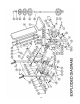
STEP 1 (See Diagram 1)
A.) Connect the two Rear Upright Beams (#1) by the Cross Brace (#2) in the mid-span. Align the
holes then secure each end of Cross Brace with one Bracket (#13), two M10 x 2 3/8” Hex
Bolts (#25), four ∅ ¾” Washers (#33), and two M10 Aircraft Nuts (#30).
B.) Insert the Backrest Adjustment Bar (#6) through the selected holes on the Rear Upright
Beams to obtain the desired Backrest incline.
C.) Attach the Left and Right Safety Hooks (#16) & (#17) to the top of the Upright Beams. Secure
each Hook with a M6 Aircraft Nut (#32).
DIAGRAM 1
4