NOTE: Please read all instructions carefully before using this product Safety Notice Hardware Identifier IGS-07 Assembly Instruction MULTI LAT/MID/LOW Machine Parts List Warranty Ordering Parts Model IGS-07 Retain This Manual for Reference 04-22-02 OWNER'S MANUAL IMPEX FITNESS PRODUCTS 14777 DON JULIAN RD., CITY OF INDUSTRY, CA 91746 Tel: (800) 999-8899 Fax: (626) 961-9966 www.impex-fitness.com info@impex-fitness.
TABLE OF CONTENTS BEFORE YOU BEGIN...................................................................................... 1 IMPORTANT SAFETY NOTICES..................................................................... 2 HARDWARE IDENTIFIER.....…....................................................................... 3 ASSEMBLY INSTRUCTIONS........................................................................... 4 EXPLODED DIAGRAM……………………………………………………………... 11 PARTS LIST………………………………………………………………………..
IMPORTANT SAFETY NOTICE PRECAUTIONS This exercise machine is built for optimum safety. However, certain precautions apply whenever you operate a piece of exercise equipment. Be sure to read the entire manual before you assemble or operate your machine. In particular, note the following safety precautions: 1. Keep children and pets away from the machine at all times. DO NOT leave children unattended in the same room with the machine. 2. Only one person at a time should use the machine. 3.
3
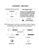
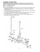
ASSEMBLY INSTRUCTION Tools Required Assembling the Machine: Adjustable Wrench and Allen Wrench NOTE: It is strongly recommended this machine to be assembled by two or more people to avoid possible injury. STEP 1 (See Diagram 1) A.) Attach the Rear Stabilizer (#33) and the Base Frame (#45) to the Main Stabilizer (#35). Secure them with two M12 x 4” Carriage Bolts (#38), ∅ 1” Washers (#12) and M12 Aircraft Nuts (#13). B.) Attach the Rear Vertical Beam (#19) to the Rear Stabilizer (#33).
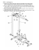
STEP 2 (See Diagram 2) A.) Align the rear of Upper Frame (#8) to the Rear Vertical Beam (#19). Attach the Top Socket Assembly (#14) to the joint. Secure it with four M12 x 3 1/8” Carriage Bolts (#11), ∅1” Washers (#12), and M12 Aircraft Nuts (#13). Do not tighten the bolts yet. B.) Place the Upper Frame onto the open bracket on the Front Vertical Beam (#22). Secure it with one M10 x 3” Allen Bolt (#44), two ∅ ¾” Washers (#43), and one M10 Aircraft Nut (#5). Securely tighten all bolts previously installed.
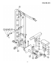
STEP 3 (See Diagram 3) A.) Insert the two Guide Rods (#18) into the holes on the Main Stabilizer (#35). Slide two Rubber Washers (#26) onto the Guide Rods from the top. NOTE: WD-40 or similar lubricant might be needed to reduce friction. B.) Slide two Guide Rod Sleeves (#28) and two Rubber Bumpers (#27) onto the Guide Rods (#18). Then slide the Weight Holder (#24) onto the two Guide Rods. At last, slide two Guide Rod Rings (#15) onto the Guide Rods. C.
DIAGRAM 3 7
STEP 4 (See Cable Loop & Diagram 4) A.) Attach the 119” Upper Cable (#10) to the front opening on the Upper Frame (#8). Make sure the ball stopper on the Cable is under the opening. B.) Attach a Pulley (#9) to the opening. Secure it with one M10 x 2 ½” Allen Bolt (#7), two Bushings (#6), and one M10 Aircraft Nut (#5). C.) Draw the Cable towards the back of the machine to the second opening on the Upper Frame. Repeat Step B above to install a Pulley. D.) Draw the Cable downward.
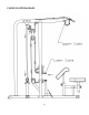
CABLE LOOP DIAGRAM 9
DIAGRAM 4 10
11
PARTS LIST KEY NO.
IRON GRIP SPORT By IMPEX FITNESS PRODUCTS LIMITED LIFE TIME WARRANTY IMPEX FITNESS PRODUCTS ("IMPEX") warrants this product to be free from defects in workmanship and material, under normal use and service conditions, for a period of LIFE TIME on the Frame and Weld, 3 YEARS on parts, and 6 MONTHS on upholstery from the date of purchase. This warranty extends only to the original purchaser. IMPEX's obligation under this Warranty is limited to replacing or repairing, at IMPEX's option.